GuestWorks and DEFINITY ECS Release 9
Technician Handbook for Hospitality Installations
555-231-743
Issue 1
November 2000
Translations and Testing
158Switch-to-INTUITY Translations
TCP/IP Signaling
The TCP/IP signaling link requires administration on both the switch and the
INTUITY. Any switch type (csi, si or r) can use a TCP/IP link. The TCP/IP link
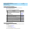
supports the PMS Interface for GuestWorks (see page 196). This section includes
procedures for testing the link.
TCP/IP Link (Switch)
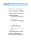
On the switch, you must do the following to administer the TCP/IP link:
1. Assign the bus bridge (
csi
systems only)
2. Assign node names
3. Assign IP interfaces
4. Assign an ethernet data module
5. Assign a processor interface channel
6. Assign IP routes (if needed).
Assign the Bus Bridge (csi Systems Only)
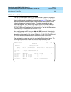
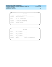
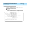
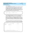
Using the change system-parameters maintenance command, Page 2, verify
that the Bus Bridge Packet Interface 2 has been enabled for the C-LAN circuit
pack. If it is not already assigned, enter the C-LAN circuit pack equipment
location, and use the defaults for the Timeslot Port fields as shown below.
change system-parameter maintenance Page 2 of 4
MAINTENANCE-RELATED SYSTEM PARAMETERS
MINIMUM MAINTENANCE THRESHOLDS ( Before Notification )
TTRs: 4 CPTRs: 1 Call Classifier Ports:
MMIs: 0 VCs:
TERMINATING TRUNK TRANSMISSION TEST (Extension)
Test Type 100: Test Type 102: Test Type 105:
ISDN MAINTENANCE
ISDN-PRI TEST CALL Extension: ISDN BRI Service SPID:
DS1 MAINTENANCE
DSO Loop-Around Test Call Extension:
LOSS PLAN (Leave Blank if no Extra Loss is Required)
Minimum Number of Parties in a Conference Before Adding Extra Loss:
SPE OPTIONAL BOARDS
Packet Intf1? y Packet Intf2? y
Bus Bridge: 03C05 Inter-Board Link Timeslots Pt0: 6 Pt1: 1 Pt2: 1


