


Test the System
8-2 Issue 1 September 1995
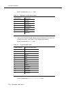
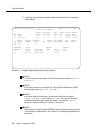
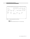
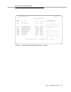
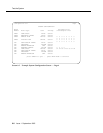
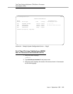
3. Verify the screen displays system status screens similar to the example
shown below:
Screen 8-1. Example System Status Screen for Cabinet 1
NOTE:
In the first section of the report, all Tone-Clocks should report a SERVICE
STATE of in.
NOTE:
In the second section of the report, all Time Division Multiplexing (TDM)
buses should report a SERVICE STATE of in.
NOTE:
In the third section of the report, all expansion links should report a
SERVICE STATE of in, and, under EXP-LINK, the cabinet/carrier/slot
numbers for the fiber optic cables are listed. For example, 01A01 in
Screen 8-1 refers to cabinet 01, carrier A, and slot 01.
NOTE:
Refer to the U.S. English book,
DEFINITY Communications System Generic
1 and Generic 3i Maintenance
, 555-104-205, for a detailed interpretation of
this screen.
status system all-cabinets Page 1 of 3 SPE A
SYSTEM STATUS CABINET 1
SELECT SPE ALARMS TONE/ SERVICE SYSTEM SYSTEM
SPE MODE SWITCH MAJOR MINOR CLOCK STATE CLOCK TONE
1A active auto 1 0 1A in standby standby
1B maint/init auto 1 0 1B in active active
SERVICE CONTROL DEDICATED SERVICE BUS ALARMS BUS OPEN BUS
TDM STATE CHANNEL TONES PKT STATE MAJOR MINOR FAULTS LEADS
1A in y n 1
1B in n y
EMERGENCY SELECT SERVICE CABINET
TRANSFER SWITCH EXP-LINK STATE MODE TYPE
1A auto-on 01A01-02A01 in standby MCC
1B auto-on 01B01-02B02 in active