


Test the System
8-14 Issue 1 September 1995
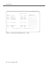
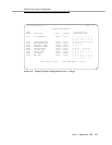
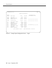
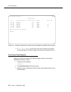
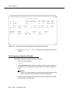
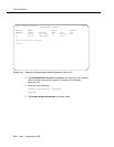
Screen 8-13. Example System Status Report for All Cabinets after Reset
10. Note the MODE for SPE 1A and 1B should have changed from that noted
in Step 4.
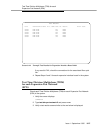
Test Expansion Interface Boards
Check each expansion interface board in the system.
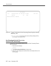
1. Verify the screen displays:
command:
2. Type test board xxx where xxx is the cabinet, carrier, and slot (see note
on page 8-1) for an expansion interface board in the system, and press
ENTER.
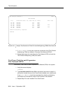
NOTE:
Labels on the port network and carrier containing the board and the
label on the strip under the board contain this information.
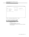
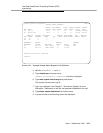
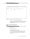
3. Verify the screen displays test results similar to the example shown below:
This example is for board 2a01.
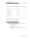
- status system all-cabinets SPE B
SYSTEM STATUS CABINET 1
SELECT SPE ALARMS TONE/ SERVICE SYSTEM SYSTEM
SPE MODE SWITCH MAJOR MINOR CLOCK STATE CLOCK TONE
1A standby auto 1 0 1A in standby standby
1B active auto 1 0 1B in active active
SERVICE CONTROL DEDICATED SERVICE BUS ALARMS BUS OPEN BUS
TDM STATE CHANNEL TONES PKT STATE MAJOR MINOR FAULTS LEADS
1A in y n 1
1B in n y
EMERGENCY SELECT SERVICE CABINET
TRANSFER SWITCH EXP-LINK STATE MODE TYPE
1A unavail 01A01-02A01 in standby MCC
1B auto-on 01B01-02B02 in active
-