


Install Fibre-Optic Cables
Issue 1 September 1995
4-19
Install Fibre-Optic Cables
This section discusses the hardware and methods required to connect and
route fibre-optic cables.
The Expansion Port Network (EPN) cabinet is normally positioned next to the
Processor Port Network (PPN) cabinet(s), but may also be installed in a different
room or a different building. Fibre-optic cables connect the cabinets together.
Fibre-Optic Cable Operation
Fibre-optic cables carry signals between the cabinets that compose your
switch. To do this, the electronic signals at the connectors on the back of a
cabinet are converted into optical signals. The optical signals from another
cabinet are then converted back into electronic signals. AT&T provides opto-
electronic devices, the 9823-type lightwave transceivers, that perform this task.
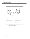
A completed signal from one cabinet goes through a transceiver, a fibre-optic
cable, and another transceiver to reach another cabinet. If the two cabinets are
close together, the optical signal may go through a single, directly connected
fibre-optic cable. If the two cabinets are far apart, it may be convenient to
connect the cabinets through the cross-connect field.
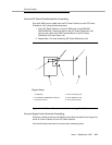
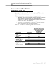
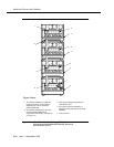
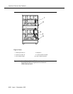
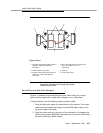
Figure 4-13 shows how to connect fibre-optic cables for direct connections.
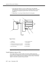
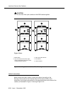
Figure 4-14 shows how to connect fibre-optic cables through a cross-connect
field. .
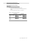
Locate Fibre-Optic Cable Connections
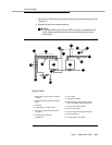
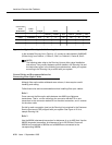
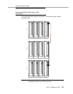
Packed with the system is a Customer Service Document (CSD) that includes an
“Inter-Cabinet Cable Running List.” Each row on the list represents a fibre-optic
cable connection.
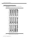
The list includes the AT&T comcode of the cable to be used, its length (in feet)
and the addresses of each cable’s source and destination. These addresses
include the numbers of the cabinets, carrier positions, and slots to which you are
to connect the cables. Use the information from the Running List to determine
where to connect each fibre-optic cable.
Figure 4-12 illustrates an example Running List.