


Plan and Prepare the Site
2-2 Issue 1 September 1995
Locate and Lay Out the Equipment
Room
Determine where the DEFINITY System Generic 3 equipment room is located,
and then lay out the equipment room floor plan for DEFINITY System cabinets,
management terminal and desk, cross-connect hardware and adjuncts, etc.
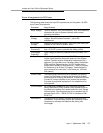
Generic 3 Management Terminal
(G3-MT) Requirements
In general, the Management Terminal must be directly connected to the cabinet
with the shortest possible cable. For maintenance purposes, the terminal must
be located in the same equipment room as the cabinet, or in sight of the cabinet.
Power for the terminal must be obtained from a single-phase standard 120 Volt
60 Hz or 230 Volt 50 Hz AC receptacle in the equipment room.
Cross-Connect Fields
Recommended hardware is the wall-mounted 110 SYSTIMAX premises
distribution equipment for structured cabling systems.
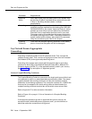
Space Requirements
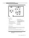
The floor plan shown in Figure 2-1 provides dimensions for the Processor Port
Network (PPN) cabinets and Cable Slack Managers.
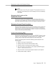
Room Layout
Typical floor plans for a single-carrier cabinet are shown below: