


Analog Station or 2-Wire Digital Station Example
Issue 1 September 1995
9-5
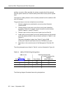
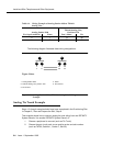
Adjunct power can be provided from the equipment room or equipment
closet with 1145B1 power unit. See "Install the 1145B1 Power Supply" on
page 9-26 for more information.
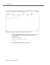
Each DEFINITY System port network can provide power for up to three
attendant consoles. This source of power is preferred for the attendant
consoles because it has the same battery backup as the system. See the
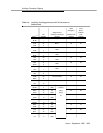
Auxiliary Power pinout information in Table 9-6 on page 9-11.
Adjunct power can be provided locally at the telephone or console by the
MSP-1 Power Supply. See "Install the MSP-1 Power Supply" on page 9-34.
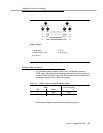
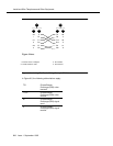
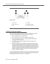
Analog Station or 2-Wire Digital
Station Example
Steps 1-3 of each example should have been completed in the Provisioning Plan
found in Chapter 2, "Plan and Prepare the Site"
,
step 8.
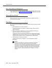
This example is typical of the 2-wire digital stations (603E, 84xx, 94xx, 302B),
2-wire analog stations (500, 2500, 71xx), analog Central Office (CO) trunks,
direct inward dialed (DID) trunks, and external alarms.
1. Choose a peripheral to connect (such as analog station or 2-wire digital
station).
2. Choose the port circuit pack to use and its carrier and slot number (from
Table 9-7 on page 9-13). (e.g., TN2183 analog line, Cabinet 1, Carrier C,
Slot 1).
3. Choose a port circuit on the port circuit pack, for example Port 3.
4. Install cross-connect jumpers to connect the named pinouts from the
analog station or 2-wire digital station to the like-named pinouts on the
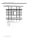
port circuit pack. This pinout information is taken from Table 9-9 for the
analog station and Table 9-8 to Table 9-9 for the TN2183 circuit pack.
5. Administer on the G3 Management Terminal (G3MT). See the DEFINITY
G3
Implementation Guide
for more details.
The wiring designations for this example are listed in Table 9-4, and are
illustrated in Figure 9-4.