


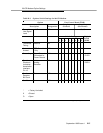

201CR Modem Option Settings
September 1995 Issue 1
H-5
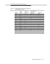
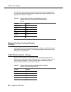
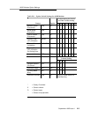
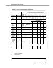
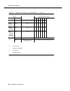
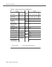
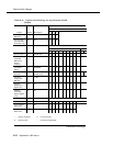
Table H-5. Options Switch Settings for 201 CR Modem
Option Line Control Board (TP1B)
Description Designation
Strap In
(Vertical)
Strap Out
(Horizontal)
Transmit
Line Signal
Level
-4 dBm ZE* 1,2,4,8
Switch Setting Digital
Board
(JB4B)12345678
Transmitter
Timing
External YD O
Automatic
Answer
DTR-Controlled
Only
YF* X
Grounding Signal Ground
Connected to
Frame Ground
YK* Install
E1-E2
Function of
Electronic
Industries
Association
Interface
Pin 18
Initiates
Analog
Receiver
YS X Install
E3-E4
Continuous
Receiver
Bit Clock
Out YP* X
Satellite In YQ* X
* = Factory furnished
X =Closed
O =Open
Continued on next page