


9-58 Issue 1 September 1995
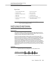
4. Administer according to the instructions in the following United States
English book:
■
DEFINITY Communications System Generic 3 V2 Implementation
,
555-230-655
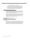
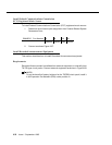
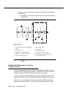
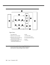
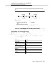
Figure 9-30. Connections for Individual Processor Data Modules
(PDM)
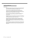
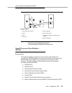
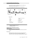
Install Call Management System
(CMS) Interface
The interface between the switch and the Call Management System (CMS) is
through Processor Data Modules (PDMs). The DEFINITY System G3i uses the
processor interface (TN765) as the required control circuit pack.
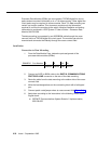
Connections between the Call Management System (CMS) interface and the
switch are covered in "Install Processor Data Modules (PDMs)" on page 9-55.
Information for connecting the Processor Data Modules (PDMs) to the Call
Management System (CMS) and setting the Processor Data Module (PDM)
2
3
8
4
9
5
10
7
6
1
12
TXT
TXR
PXT
PXR
11
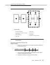
1. Z3A1 or Z3A2 Asynchronous Data Unit
(ADU)
2. Information outlet
3. Satellite site, or adapter location
4. Station side and blue or white field
5. Switch side and purple field
6. Blue or white field
7. Purple field
8. Cross-connect field
9. Digital line circuit pack (TN754)
■ Other digital-line circuit packs may be
used in some countries.
Figure Notes: