


Connect System Cabinet Grounds
Issue 1 September 1995
4-3
Connect System Cabinet Grounds
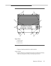
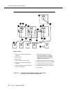
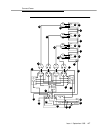
To connect ground, refer to Figure 4-2 on page 4-4 and perform the following:
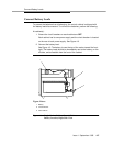
1. At lower left rear of the Processor Port Network (PPN) cabinet (Control
Cabinet A), connect a 6 AWG ground wire to the cabinet ground block.
See Appendix F for international wire conversions for outside North
America.
NOTE:
A screwdriver is required to loosen and tighten the screws securing
the ground wire to the ground block.
2. Run the ground wire to an approved ground. Refer to Appendix A.
3. At the Expansion Port Network (EPN) cabinet(s) (as provided), connect a
6 AWG ground wire to the A-cabinet ground block.
4. Run the ground wire from the Expansion Port Network (EPN) to the
Processor Port Network (PPN) cabinet and connect it to the cabinet
ground block.
NOTE:
If the Expansion Port Network (EPN) cabinet is remotely located
from the Processor Port Network (PPN) cabinet (in a separate room
or building), run the 6 AWG cabinet ground wire to an approved
protective ground.
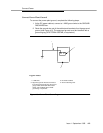
5. At the Processor Port Network (PPN) cabinet, connect a 10-AWG wire to
the cabinet ground block. At a later time, tie-wrap the ground wire
(coupled bonding conductor) to the trunk cables, terminating it at the
coupled bonding conductor terminal bar at the cross-connect field for the
switch. Refer to Figure 4-9 on page 4-13 for an illustration of the coupled
bonding conductor.