


Connect Generic 3 Management Terminal (G3-MT)
Issue 1 September 1995
6-5
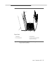
7. Connect AC power cord of the terminal to the selected AC receptacle in
the equipment room and turn on the terminal.
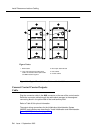
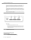
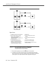
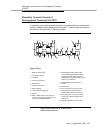
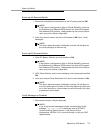
Figure 6-3. Duplication Optional Terminal and Terminal
Connectors on the Control Cabinets
Figure 6-3 shows the two possible positions on the back of the switch control
cabinet for connecting the M25B cord between the switch and the terminal; or,
for DC powered systems and for electromagnetic shielding,
for installing the
116A Electronic Industries Association (EIA) Ground Isolator: the DUPLICATION
OPTION TERMINAL connector for high and critical reliability (duplicated)
systems in the top illustration and the TERMINAL connector for standard
reliability (unduplicated) systems in the bottom illustration.
TERMINAL TERMINAL
DUPLICATION
OPTION
PROCESSOR
INTERFACE
DATA
COMMUNICATIONS
EQUIPMENT
TERMINAL TERMINAL
DUPLICATION
OPTION
PROCESSOR
INTERFACE
DATA
COMMUNICATIONS
EQUIPMENT