


Install Multipoint Adapters
Issue 1 September 1995
9-45
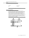
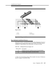
Figure Notes:
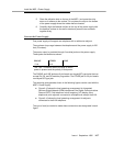
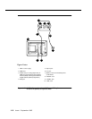
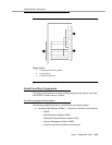
Figure 9-21. Diagram of 367A
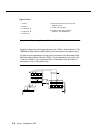
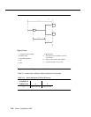
Basic Multipoint Installation Distances
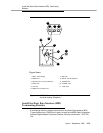
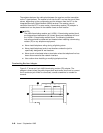
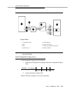
Figure 9-22, Table 9-11 and Table 9-12 provide cabling distances for fan-out of
Integrated Services Digital Network Basic Rate Interface (ISDN-BRI) multipoint
installations. Cabling distances are abbreviated in the figure as follows:
In Table 9-10, the terminating resistor (TR) is located in the closet. All distances
assume 24-gauge D-Inside Wire (DIW).
Table 9-10. Cabling Distances for Figure 9-22
Abbreviation Description
A Distance from the T-interface source to the work location
B Distance from the closet to the work location
C Less than 33 feet (10 meters) of cord
31 2
88 877 766 655 544 433 322 211 1
4
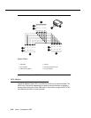
1. Jack 1
2. Jack 2
3. Jack 8
4. 367A Adapter