


Install and Connect the Cabinets
4-4 Issue 1 September 1995
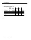
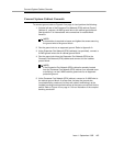
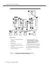
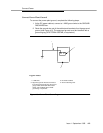
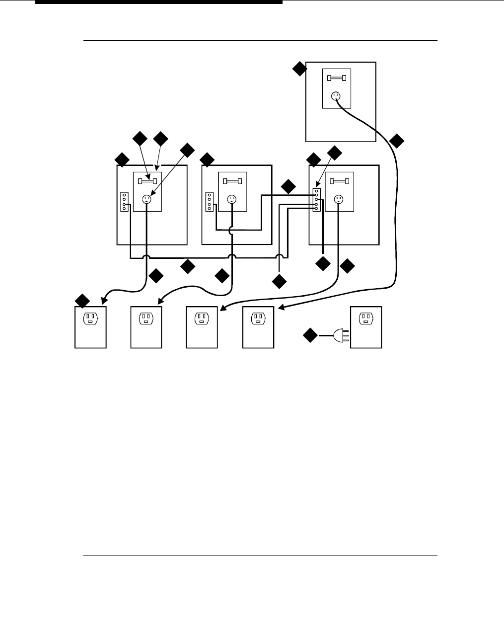
Figure 4-2. Typical AC Power and Grounding Arrangement
for Single-Carrier Cabinet (Rear View)
ON ON
OFF OFF
ON ON
OFF OFF
ON ON
OFF OFF
ON ON
OFF OFF
8
13
9
5
10
6
11
7
7 7
7
12
12
1 1
3
4
2
1. Expansion Port Network (EPN) Control
Cabinet A
2. Circuit breaker
3. Power supply
4. Power receptacle in power supply
5. Processor Port Network (PPN) Control
Cabinet A
6. Cabinet-stack single-point ground block
7. Power cord 2.5 meters
8. National Electrical Manufacturer’s
Association (NEMA) 5-15 or National
Electrical Manufacturer’s Association
(NEMA)5-20 receptacle or equivalent
locally provided receptacles
9. 6 AWG ground wire to approved ground
10. Generic 3 Management Terminal (G3-MT)
11. 10 AWG Coupled Bonding Conductor
12. 6 AWG cabinet-stack ground conductor
13. Port cabinet
Figure Notes: