


Test the System
8-4 Issue 1 September 1995
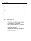
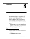
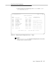
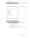
Screen 8-3. Example System Status Screen for Cabinet 3
NOTE:
See the notes associated with Screen 8-1 on the previous page.
NOTE:
In the example of Screen 8-3, cabinet 3 (the second Expansion Port
Network (EPN)) is not connected to the system.
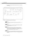
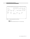
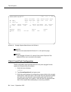
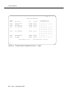
Check Circuit Pack Configuration
The list configuration report provides a list of circuit packs plugged into the
system and recognized by the software.
1. Verify the screen displays:
command:
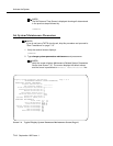
2. Type list configuration all and press
ENTER.
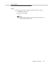
3. Verify the screen displays list configuration screens similar to the example
shown below. Check the report on the screen with the equipment installed
and make sure the software is communicating with each circuit pack
(except power supply circuit packs). Wait until after the diagnostic tests
later in this chapter before attempting to correct any problems.
status system all-cabinets Page 3 of 3 SPE A
SYSTEM STATUS CABINET 3
SELECT SPE ALARMS TONE/ SERVICE SYSTEM SYSTEM
SPE MODE SWITCH MAJOR MINOR CLOCK STATE CLOCK TONE
1A active auto 1 0 3A
1B maint/init auto 1 0 3B
SERVICE CONTROL DEDICATED SERVICE BUS ALARMS BUS OPEN BUS
TDM STATE CHANNEL TONES PKT STATE MAJOR MINOR FAULTS LEADS
3A
3B
EMERGENCY SELECT SERVICE CABINET
TRANSFER SWITCH EXP-LINK STATE MODE TYPE
3A -