


9-40 Issue 1 September 1995
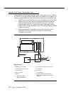
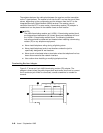
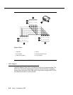
The resistors balance the cable plant between the receiver and the transmitter
on the T-type interface. The resistor is built into the NT1 and can be one of three
values, depending on the configuration and the distance from the NT1 to the
Integrated Services Digital Network (ISDN) terminal. The resistor value is
controlled from the NT1. In some cases, a terminating resistor (TR) adapter is
needed and can be placed in the satellite closet or work location.
NOTE:
The 440A4 terminating resistor and 110RA1-12 terminating resistor block
are Underwriters Laboratories (UL) listed. Most new installations will be of
the 110RA1-12 terminating resistor block. The following installation
instructions should be observed and heeded when installing a terminating
resistor (TR) or any telephone equipment.
■ Never install telephone wiring during a lightning storm.
■ Never install telephone jacks in wet locations unless the jack is
specifically designed for wet locations.
■ Never touch uninsulated wires or terminals unless the telephone line has
been disconnected at the network interface.
■ Use caution when installing or modifying telephone lines.
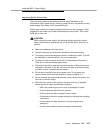
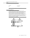
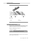
Terminating Resistor Adapter
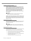
Figure 9-17 shows an 8-pin 440A4 terminating resistor (TR) adapter. The
adapter is three inches long with plugs at both ends and a short cord to connect
the 8-conductor jack. When is connected, a small screwdriver is needed for
removal.
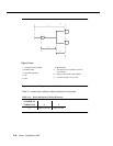
1
2
3
4
5
6
7
8
1
2
3
4
5
6
7
8
3
4
1
2
RRCC