


Install Customer-Provided Terminal Using
Asynchronous Data Unit (ADU)
Issue 1 September 1995
9-61
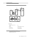
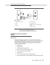
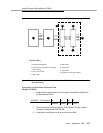
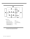
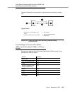
Figure 9-32. Connections to Asynchronous Data Unit (ADU) for
Data Terminal Equipment (DTE)
Install Customer-Provided Terminal
Using Asynchronous Data Unit (ADU)
Requirements
The interface between the switch and the customer’s data terminals and host
computer can be through Processor Data Modules (PDMs). Refer to section on
installing Processor Data Modules (PDMs) for details.
Asynchronous data terminals, however, can be connected through a Z3A
Asynchronous Data Unit (ADU) to a TN726B data line circuit pack (Figure 9-32).
Normally, the data unit is powered from the connected data terminal. The data
unit can also be remotely or locally powered using a 2012D transformer
equipped with a 248B adapter. Data units connected to receive-only printers
always require external power. The need for external power must be determined
experimentally for data units connected to other devices. For more information
on data unit installation, refer to the
Z3A Asynchronous Data Unit User’s Manual
,
555-401-701.
Installation
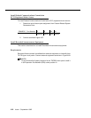
1. Determine data unit port assignment from Data Module Form:
2. Connect the RS-232 plug on the data unit to the data terminal.
EXAMPLE: Port Number 2 B 02 01
Cabinet Carrier Slot Circuit
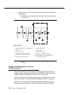
1. Processor Data Module PDM)
2. Information outlet
3. Satellite site, or adapter location
4. Station side
5. Switch side
6. Digital Line Circuit Pack (TN754)
7. Purple field
8. Patch cord or jumpers
9. Blue or white field
10. Four pair line cord
11. Four pair line cord
12. Part of Cross-connect field
■ Other data-line circuit packs may be
used in some countries.
Figure Notes: