


Issue 1 September 1995 5-3
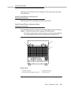
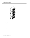
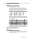
In Figure 5-1, approximately 576 4-Pair or 768 3-Pair Station Capacity is
illustrated.
Hardware Installation
These hardware installation instructions are written so one system technician
can install the following equipment:
■ Cross-connect field
■ Cable slack managers
■ Sneak current protector (507B)
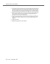
The preferred cross-connect field location is directly behind the switch cabinet.
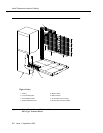
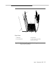
Install Cable Slack Managers
To install the cable slack managers (Figure 5-2), proceed as follows:
1. Place the Z113A cable slack manager against the wall under the cross-
connect field, aligning the left side of the cable slack manager with the
first terminal block of the trunk/auxiliary field.
2. Place the next cable slack manager beside the previous cable slack
manager. Align the tabs and interlocks and snap the cable slack
managers together.
3. Repeat Step 2 until all cable slack managers are installed.
NOTE:
Nine holes (1/4-inch or 0.6 cm) are provided in a cable slack manager
base for earthquake mounting. Also, if a cable slack manager base is
mounted on an uneven floor, shims may be required to level it and insure
proper fit of the covers. Holes are provided in the sides of the base for
bolting cable slack managers together. Bolts and shims are not provided.
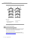
Route Cables from Cabinet to Cross-
Connect Field
Use the following guidelines when routing cables from the cabinet to the cross-
connect field.
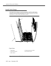
■ When cable routing is to the top/bottom of the cross-connect field, each
port cable is connected at the cabinet and routed along the front trough
of the cable slack manager to the connecting/terminal block. The cable is
then terminated.
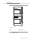
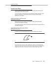
■ Enough slack must be left at the cabinet end of the cable to allow for
proper dressing of the cables (Figure 5-3).