


Plan and Prepare the Site
2-6 Issue 1 September 1995
Lay Out and Ensure Appropriate Power
1. Lay out and ensure appropriate power for switch cabinets and
management terminal in equipment room.
2. Provide one power outlet per single-carrier cabinet.
3. Have an electrician check the commercial power and verify power is
available and present.
Power Arrangements for AC Power
The following procedures apply to both the Processor Port Network (PPN)
cabinet(s) and Expansion Port Networks (EPN) cabinet(s) (as provided), except
where noted.
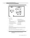
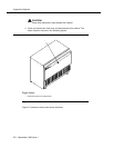
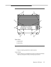
The following illustration shows a typical power and grounding layout, and the
illustration after that shows the AC power receptacle requirements. The power
circuit must be dedicated to the DEFINITY System Generic 3 only and must be
on a separately current limited (fuse or circuit breaker) circuit. It must not be
shared with other equipment and must not be under the control of a wall switch.
The power supply for the Generic 3 Management Terminal (G3-MT), however,
does not have to be dedicated
Locate and/or arrange the cross-connect field so all power receptacles are
accessible.