


Install and Wire Telephones and Other Equipment
9-2 Issue 1 September 1995
auxiliary connector. When possible, the primary console should be powered
from the system cabinet so it has the same power failure backup as the system
itself.
The maximum cabling distance for the console powered from the cabinet is 350
feet (100 meters).
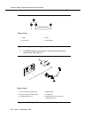
The general steps to connect a telephone are as follows:
1. Choose a telephone or peripheral to connect such as Attendant
Console 302B.
2. Choose the port circuit pack to use (from circuit pack information
provided in Table 9-7 on page 9-13) and its carrier and slot number.
(TN754, Cabinet 1, Carrier C, Slot 02).
3. Choose a port circuit on the port circuit pack (such as Port 05).
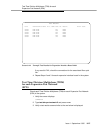
4. Install cross-connect jumpers to wire the named pinouts on the terminal
to the like-named pinouts on the port board, as shown in Table 9-1 and
Figure 9-1.
This pinout information is taken from Table 9-7 for the 302B
(4-wire) and Table 9-8 and Table 9-9 for the TN754B circuit pack.
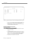
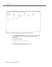
5. Administer on the console screen of the Management Terminal (G3-
MT).
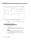
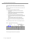
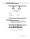
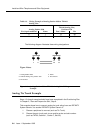
The wiring designations are listed in Table 9-1 and are illustrated in Figure 9-1.
The following diagram illustrates these wiring designations.
Table 9-1. 302B to TN754 Wiring Designations
302B, 4-wire TN754 (position 1C02)
Pin
(from Table 9-7) Name Port 5 Name
4-wire Connector Pin
Number
(from Table 9-9)
1 txt txt5 39
2 txr txr5 14
3 pxt pxt5 40
6 pxr pxr5 15