


Install and Wire Telephones and Other Equipment
9-20 Issue 1 September 1995
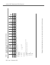
This page left intentionally blank so you can remove the pinout chart from the book if necessary.
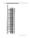
V-S 50
S-V 25
† The wire colors in this pinout chart apply only to B25A and A25B cables. H600-307,60 cable colors are not shown.
Within this chart, the following abbreviations apply for analog tie trunks:
T,R PBX transmit voice
T1,R1 PBX receive voice
M PBX transmit signal
E PBX receive signal
PX PBX transmit T Tip (A) Green
TX Terminal transmit R Ring (B) Red
S Sleeve
LI, LI* Digital Trunk IN
LO, LO*
Digital Trunk OUT
1 Color designation is AA-BB, where AA is the main wire color, and BB is the color of the short
stripe on the wire.
2 For translation purposes, the following wire colors apply in the above table:
W White
BL Blue
O Orange
G Green
BR Brown
S Slate (Grey)
R Red
BK Black
Y Yellow
V Violet
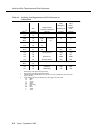
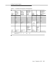
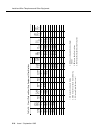
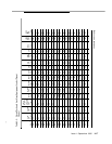
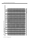
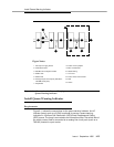
Table 9-9. Circuit Pack and Auxiliary Equipment Leads (Pinout
Charts) — Continued
Color
1,2
Conn.
Pin
Numbers
Analog
Line
8 ports
2-Wire
Digital
Line and
Analog
Line
16 ports
Data
Line
Digital
Line
4-wire
Hybrid
Line
MET
Line
AUX
Trk.
CO
Trk.
CO
Trk.
3-wire
DID/
DIOD
Trk.
Tie
Trk.
DS1
Tie
Trk.
ISDN
BRI
Line
4-wire
ISDN
BRI
Line
2-wire
Continued on next page