


Install Emergency Transfer Units and Associated
Telephones
Issue 1 September 1995
9-23
Install Emergency Transfer Units and
Associated Telephones
Emergency transfer capability is provided by a transfer unit mounted on the wall
next to the trunk/auxiliary cross-connect field.
Analog telephones can be used for emergency transfer. The 500-and 2500-type
telephones can also be used as normal extensions. Emergency transfer
capability may be provided on Central Office (CO) trunks.
The following transfer units are available:
■ The 808A Emergency Transfer Panel provides emergency trunk bypass
or power-fail transfer for up to five incoming analog Central Office (CO)
trunk loops to five selected private branch exchange analog single line
telephones. When a power failure or other system problem interrupts
service, the sets are automatically and directly connected to the Central
Office trunks and are available for emergency use outside the private
branch exchange service environment.
When a telephone connected to the 808A goes off-hook during bypass,
circuitry inside the panel places signalling on the Central Office (CO)
trunk causing the Central Office (CO) to return dial tone. Each 808A
bypass circuit can be switched to either loop start or ground start
signalling.
■ The 574-5 power transfer unit serves up to five power failure transfer
telephones. The unit provides automatic ground start.
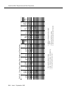
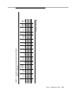
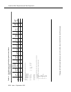
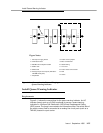
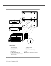
At the cross-connect field, the transfer units are connected to a yellow terminal
row/connecting block in the trunk/auxiliary field. The units are powered (-48VDC)
from the EM TRANS RELAY PWR terminals. Refer to Figure 9-6 for pinout
information. There are seven EM TRANS RELAY PWR terminal pairs to provide
power to up to seven transfer units.
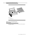
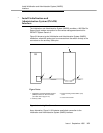
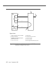
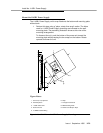
Install the 808A Emergency Transfer Panel
The 808A is connected to the cross-connect field through a B25A or A25B
cable. Install the 808A Emergency Transfer Panel according to the instructions
packed with the unit.