


Install and Connect the Cabinets
4-6 Issue 1 September 1995
Connect Power
Connect either AC or DC power as described in this section.
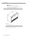
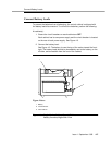
Verify the label near the circuit breaker on the power supply toward the rear of
each cabinet corresponds to your local voltage type.
!
DANGER:
If the label is different than the voltage type at your site, notify your A T & T
representative immediately for a replacement power supply. Do not, under
any circumstances, connect to power!
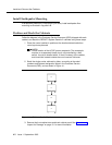
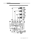
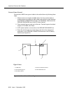
Connect AC Power
Figure 4-2 applies to multiple Processor Port Networks (PPN) and Expansion
Port Network (EPN) cabinet arrangements. If multiple Expansion Port Network
(EPN) cabinets are required, you must provide the receptacles for the 4-cabinet
Processor Port Network (PPN) arrangement in addition to the receptacles for a
2-, 3-, or 4-cabinet Expansion Port Network (EPN) arrangement. Provide one
receptacle per single-carrier cabinet.
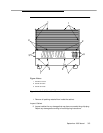
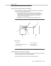
1. Verify the circuit breakers are OFF .
2. Connect cabinet AC line cords to the AC power receptacles. The AC line
cords for the cabinets must first be connected to the cabinets and then to
the AC power receptacles.
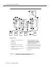
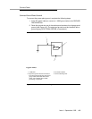
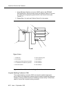
Connect DC Power
The following procedures apply to both the Processor Port Networks (PPN) and
Expansion Port Networks (EPN).
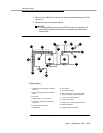
Figure 4-4 shows a typical power and grounding layout for a DC-powered
single-carrier cabinet. The size of the wire required for the -48 VDC and -48 volt
return must ensure the -48 VDC supplied by the battery plant to the cabinets will
be maintained between -42.5 and -52.5 volt DC. This ensures proper operation
and prevents hardware damage.