


Install and Connect the Cabinets
4-20 Issue 1 September 1995
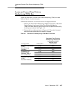
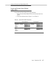
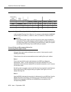
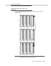
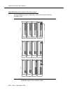
Figure 4-12. Typical Fibre-Optic Cable Running List
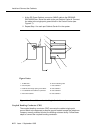
In the example Running List in Figure 4-12, connect a cable labeled 104266465
(20 feet long) from Cabinet 1, Carrier C, Slot 2, to Cabinet 2, Carrier B, Slot 2.
NOTE:
The following tasks refer to the Running List and offer typical installation
instructions. If any conflict between specific details in the Running List and
the instructions given in the following procedures arise, cable your system
according to the Running List provided with your system.
General Rules and Recommendations for
Connecting Fibre-Optic Cables
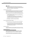
Although fibre-optic cables withstand some misuse, it does require careful
handling and routing.
Follow these rules and recommendations when installing fibre-optic cables:
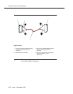
Rule 1
Cross-connect the fibre-optic cable between two 9823-type lightwave
transceivers. That is, run the cable from the connector marked TX on one
transceiver to the connector marked RX on the other transceiver, and in reverse
for the other cable.
Do this for each connection (row) on the Running List contained in the Customer
Service Document (CSD) shipped with your system. See Figure 4-12 for a
sample Running List.
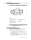
Rule 2
Use the 9823A (shortwave) transceiver for distances of up to 4900 feet. Use the
9823B (longwave) transceiver for distances of up to 25,000 feet. Ensure all
9823As are connected to 9823As and all 9823Bs are connected to the
corresponding 9823Bs.
Connection
From
SD67975-01
Cable
Code Length From To
Cabinet Position Slot Cabinet Position Slot
CAD3 104266465 20 ft. 01 C 02 02 B 02
CAD3 104266465 20 ft. 01 D 02 02 A 01