


Install and Connect the Cabinets
4-12 Issue 1 September 1995
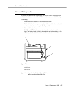
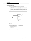
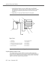
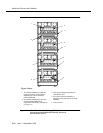
1. At the DC Power Cabinet, connect a 6 AWG cable to the GROUND
DISCHARGE bar. Route the cable to the port Cabinet Carrier A. Connect
the cable to the single-point ground block in the Control Carrier (see
Figure 4-7).
2. Repeat Step 1 for each port Cabinet Carrier A in the system.
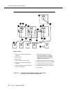
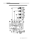
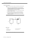
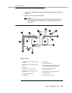
Figure 4-8. Ground Connection for Single-Carrier Network
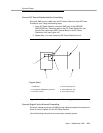
Coupled Bonding Conductor (CBC)
The coupled bonding conductor (CBC) connects the cabinet single-point
ground block to the approved protective ground located nearest the (telephone
company owned) protector block at the building entrance facility. Follow these
steps to connect the coupled bonding conductor:
1
2
3
4
5
6
7
8
9
10
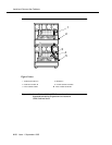
1. 6 AWG wire
2. Ground plate
3. Cabinet stack single point ground block
4. To additional Port Cabinet as provided
5. DC Power Cabinet
6. Ground discharge bar
7. Port Cabinet D
8. Port Cabinet C
9. Port Cabinet B
10. Port Cabinet A
Figure Notes: