


Install Telecommunications Cabling
5-6 Issue 1 September 1995
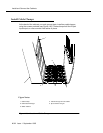
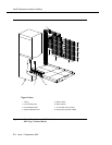
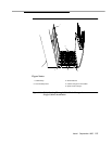
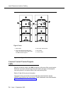
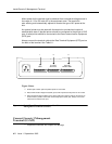
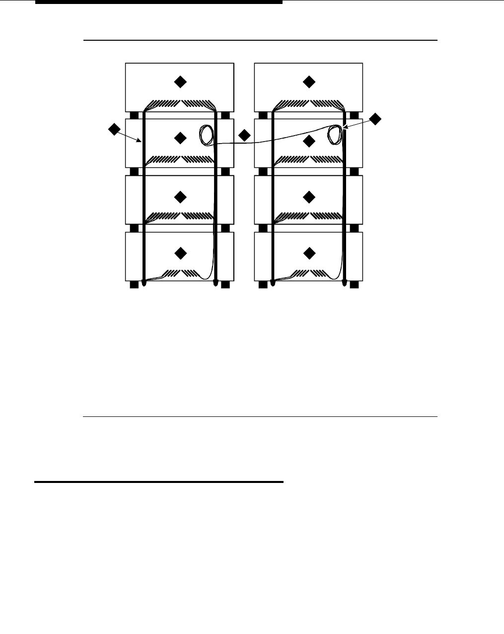
Figure 5-3. Typical Port Cable Installation at Switch Cabinet
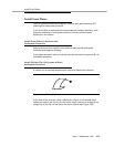
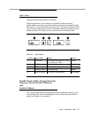
Connect Control Carrier Outputs
Cable
Plug the connector cable in the AUX connector on the rear of the control carrier.
Route the connector cable through the cable slack manager to the assigned
connecting block in the yellow field of the trunk/auxiliary field.
Refer to Table 9-9 for pinout information.
The output wiring connections for the Initialization Administration System
(INADS) trunk interface are described in "Install Initialization and Administration
System (INADS) Interface" on page 9-21
.
3
4
4
4
4
4
4
5 5
1
2
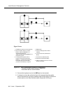
1. B25A cables
2. Loop and Drape Excess Fibre-Optic
Cable. Do Not Route Fibre-Optic Cable
and B25A Cables Together.
3. Fibre-Optic Cable Sheath
4. Port Cabinet
5. Control cabinet
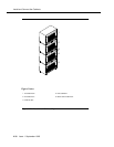
Figure Notes: