


Install Generic 3 Management Terminal
6-4 Issue 1 September 1995
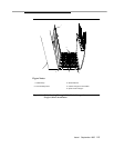
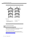
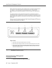
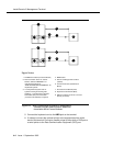
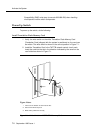
Figure 6-2. Direct Connections to Generic 3-Management
Terminal (G3-MT) and Electronic Industries
Association (EIA) Ground Isolator
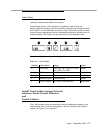
5. Connect the keyboard cord to the KBD jack on the terminal.
6. If ordered, connect the optional printer to the appropriate place at the
back of the terminal. Connect a parallel printer to the printer or PAR port or
a serial printer to the Data Communication Equipment (DCE) port.
7
3
3
4
4
9
9
5
5
1
2
2
6
8
1. TN786B Circuit Pack (Processor Board)
2. Rear Connection Panel “A” Carrier
Position, labeled “TERMINAL” for
unduplicated systems or
“DUPLICATION OPTION TERMINAL” for
duplicated systems.
3. In a DC-powered system and for
systems needing electromagnetic
shielding, a 116 Electronic Industries
Association (EIA) Ground Isolator
(comcode 106 005 242) is required
4. M25B Cable
5. Generic 3 Management Terminal
(G3-MT)
6. TN775 Circuit Pack (Maintenance
Board)
7. Processor Port Network (PPN)
8. Expansion Port Network (EPN)
9. Distance between units not to exceed
50 feet (18 meters)
Figure Notes: