


89
V/F pattern
4
PARAMETERS
4.5 V/F pattern
4.5.1 Base frequency, voltage (Pr. 3, Pr. 19, Pr. 47)
* The parameters can be set when Pr. 160 User group read selection = "0" (Refer to page 190)
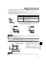
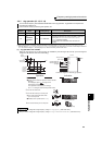
(2) Set multiple base frequencies (Pr. 47)
⋅ When you want to change the base frequency when switching two motors with one inverter, use the Pr. 47 Second V/F
(base frequency).
⋅ Pr. 47 Second V/F (base frequency) is valid when the RT signal is ON.
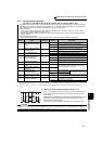
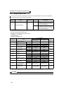
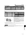
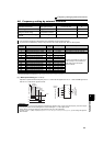
Purpose Parameter that must be Set Refer to Page
Set motor ratings
Base frequency, base
frequency voltage
Pr. 3, Pr. 19, Pr. 47 89
Select a V/F pattern according to
applications
Load pattern selection Pr. 14 91
Use special motor Adjustable 5 points V/F Pr. 71, Pr. 100 to Pr. 109 92
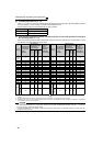
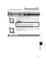
Used to adjust the inverter outputs (voltage, frequency) to the motor rating.
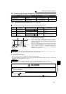
Parameter
Number
Name Initial Value Setting Range Description
3 Base frequency 60Hz 0 to 400Hz
Set the frequency when the motor
rated torque is generated. (50Hz/60Hz)
19
*
Base frequency voltage 9999
0 to 1000V Set the base voltage.
8888 95% of power supply voltage
9999 Same as power supply voltage
47
*
Second V/F (base frequency) 9999
0 to 400Hz
Set the base frequency when the RT
signal is ON.
9999 Second V/F invalid
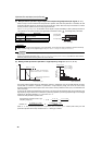
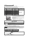
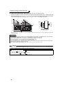
(1) Setting of base frequency (Pr. 3)
⋅ When operating a standard motor, generally set the rated
frequency of the motor to Pr. 3 Base frequency. When running
the motor using bypass operation, set Pr. 3 to the same value
as the power supply frequency.
⋅ If the frequency given on the motor rating plate is "50Hz" only,
always set to "50Hz". Leaving the base frequency unchanged
from "60Hz" may make the voltage too low and the torque
insufficient. It may result in an inverter trip due to overload.
Caution must be taken especially when Pr. 14 Load pattern
selection = "1" (variable torque load).
⋅ When using the Mitsubishi constant-torque motor, set Pr. 3 to
60Hz.
REMARKS
⋅ The RT signal acts as the second function selection signal and makes the other second functions valid. (Refer to page 125)
⋅ In the initial setting, the RT signal is assigned to the RT terminal. By setting "3" to any of Pr. 178 to Pr. 189 (Input terminal function
selection), you can assign the RT signal to the other terminal.
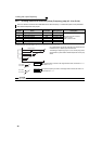
Pr.19
Output voltage (V)
Output frequency
(Hz)
Pr.3
Pr.47