


41
Connection of stand-alone option units
2
WIRING
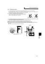
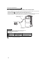
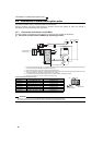
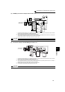
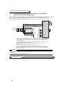
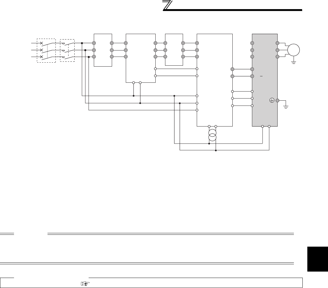
(2) Connection with the MT-HC (FR-F720-03160 (FR-F740-01800) or more)
*1 Remove the jumper across terminals R and R1, S and S1 of the inverter, and connect the control circuit
power supply to the R1 and S1 terminals. Do not connect anything to the power input terminals R/L1, S/
L2, T/L3. Incorrect connection will damage the inverter. (E.OPT (option fault) will occur. (Refer to page 342.)
*2 Do not insert the MCCB between terminals P/+ and N/- (P/+ and P/+, N/- and N/-). Opposite polarity of
terminals N, P will damage the inverter.
*3 Use Pr. 178 to Pr. 189 (input terminal function selection) to assign the terminals used for the X10 (X11) signal.
(Refer to page 122.) For communication where the start command is sent only once, e.g. RS-485
communication operation, use the X11 signal when making setting to hold the mode at occurrence of an
instantaneous power failure. (Refer to page 114.)
*4 Connect the power supply to terminals R1 and S1 of the MT-HC via an isolated transformer.
*5 Be sure to connect terminal RDY of the MT-HC to the X10 signal or MRS signal assigned terminal of the
inverter, and connect terminal SE of the MT-HC to terminal SD of the inverter. Without proper connecting,
MT-HC will be damaged.
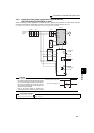
CAUTION
⋅ Use sink logic (initial setting) when the MT-HC is connected. The MT-HC cannot be connected when source logic is
selected.
⋅ The voltage phases of terminals R/L1, S/L2, T/L3 and terminals R4, S4, T4 must be matched.
⋅ When connecting the inverter to the MT-HC, do not connect the DC reactor provided to the inverter.
♦ Parameters referred to
Pr. 30 Regenerative function selection Refer to page 114
Three-phase
A
C power
supply
MCCB
MT-HCL01 MT-HCB
R1 S1
R1 S1
R1/
L11
S1/
L21
MT-HCL02 MT-HC Inverter
MT-HCTR
Isolated transformer
R
S
T
R/L1
S/L2
T/L3
U
V
W
R2
S2
T2
R2
S2
T2
R3
S3
T3
R3
S3
T3
R4
S4
T4
R4
S4
T4
R
S
T
88R
88S
88R
88S
*2
RDY
RSO
SE
X10
RES
SD
*3
*5
*1
*1
*4
Motor
IM
P
N
P/+
N/
MC