


22
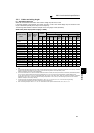
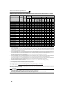
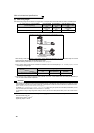
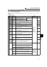
Main circuit terminal specifications
400V class (when input power supply is 440V based on the rated current for 110% overload for 1 minute)
The line voltage drop can be calculated by the following formula:
Line voltage drop [V]=
Use a larger diameter cable when the wiring distance is long or when it is desired to decrease the voltage drop (torque
reduction) in the low speed range.
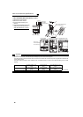
Applicable Inverter Model
Terminal
Screw Size
*4
Tightening
Torque N·m
Crimping
(Compression)
Terminal
Cable Sizes
HIV, etc. (mm2) *1 AWG/MCM *2 PVC, etc. (mm2) *3
R/L1,
S/L2,
T/L3
U, V, W
R/L1,
S/L2,
T/L3
U, V, W
P/+, P1
Earth
(ground)
cable
R/L1,
S/L2,
T/L3
U, V, W
R/L1,
S/L2,
T/L3
U, V, W
Earth
(ground)
cable
FR-F740-00023 to 00083-NA M4 1.5 2-4 2-4 2 2 2 2 14 14 2.5 2.5 2.5
FR-F740-00126-NA M4 1.5 2-4 2-4 2 2 3.5 3.5 12 14 2.5 2.5 4
FR-F740-00170-NA M4 1.5 5.5-4 5.5-4 3.5 3.5 3.5 3.5 12 12 4 4 4
FR-F740-00250-NA M4 1.5 5.5-4 5.5-4 5.5 5.5 5.5 8 10 10 6 6 10
FR-F740-00310-NA M5 2.5 8-5 8-5 8 8 8 8 8 8 10 10 10
FR-F740-00380-NA M5 2.5 14-5 8-5 14 8 14 14 6 8 16 10 16
FR-F740-00470-NA M6 4.4 14-6 14-6 14 14 22 14 6 6 16 16 16
FR-F740-00620-NA M6 4.4 22-6 22-6 22 22 22 14 4 4 25 25 16
FR-F740-00770-NA M6 4.4 22-6 22-6 22 22 22 14 4 4 25 25 16
FR-F740-00930-NA M8 7.8 38-8 38-8 38 38 38 22 1 2 50 50 25
FR-F740-01160-NA M8 7.8 60-8 60-8 60 60 60 22 1/0 1/0 50 50 25
FR-F740-01800-NA M8 7.8 60-8 60-8 60 60 60 38 1/0 1/0 50 50 25
FR-F740-02160-NA M10 14.7 100-10 100-10 80 80 80 38 3/0 3/0 70 70 35
FR-F740-02600-NA M10 14.7 100-10 100-10 100 100 100 38 4/0 4/0 95 95 50
FR-F740-03250-NA M10 14.7 150-10 150-10 125 125 100 38 250 250 120 120 70
FR-F740-03610-NA M10 14.7 150-10 150-10 150 150 150 38 300 300 150 150 95
FR-F740-04320-NA
M12(M10)
24.5 100-12 100-12 2×100 2×100 2×100 38 2×4/0 2×4/0 2×95 2×95 95
FR-F740-04810-NA
M12(M10)
24.5 100-12 100-12 2×100 2×100 2×100 38 2×4/0 2×4/0 2×95 2×95 95
FR-F740-05470-NA
M12(M10)
46 150-12 150-12 2×125 2×125 2×125 38 2×250 2×250 2×120 2×120 120
FR-F740-06100-NA
M12(M10)
46 150-12 150-12 2×150 2×150 2×125 60 2×300 2×300 2×150 2×150 150
FR-F740-06830-NA
M12(M10)
46 200-12 200-12 2×200 2×200 2×150 60 2×350 2×350 2×185 2×185 2×95
FR-F740-07700-NA
M12(M10)
46 C2-200 C2-200 2×200 2×200 2×200 60 2×400 2×400 2×185 2×185 2×95
FR-F740-08660-NA
M12(M10)
46 C2-250 C2-250 2×250 2×250 2×200 60 2×500 2×500 2×240 2×240 2×120
FR-F740-09620-NA
M12(M10)
46 C2-250 C2-250 2×250 2×250 2×250 100 2×500 2×500 2×240 2×240 2×120
FR-F740-10940-NA
M12(M10)
46 C2-200 C2-200 3×200 3×200 3×200 100 3×350 3×350 3×185 3×185 2×150
FR-F740-12120-NA
M12(M10)
46 C2-200 C2-200 3×200 3×200 3×200 100 3×400 3×400 3×185 3×185 2×150
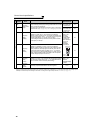
*1 For the FR-F740-01160 or less, the recommended cable size is that of the cable (e.g. HIV cable (600V class 2 vinyl-insulated cable)) with continuous
maximum permissible temperature of 75°C (167°F). Assumes that the surrounding air temperature is 50°C (122°F) or less and the wiring distance is
20m (65.62feet) or less.
For the FR-F740-01800 or more, the recommended cable size is that of the cable (e.g. LMFC (heat resistant flexible cross-linked polyethylene
insulated cable)) with continuous maximum permissible temperature of 90°C (194°F). Assumes that the surrounding air temperature is 50°C (122°F)
or less and wiring is performed in an enclosure.
*2 For the FR-F740-00930 or less, the recommended cable size is that of the cable (THHW cable) with continuous maximum permissible temperature of
75°C (167°F). Assumes that the surrounding air temperature is 40°C (104°F) or less and the wiring distance is 20m (65.62feet) or less.
For the FR-F740-01160 or more, the recommended cable size is that of the cable (THHN cable) with continuous maximum permissible temperature of
90°C (194°F). Assumes that the surrounding air temperature is 40°C (104°F) or less and wiring is performed in an enclosure.
(Selection example for use mainly in the United States.)
*3 For the FR-F740-00930 or less, the recommended cable size is that of the cable (PVC cable) with continuous maximum permissible temperature of
70°C (158°F). Assumes that the surrounding air temperature is 40°C (104°F) or less and the wiring distance is 20m (65.62feet) or less.
For the FR-F740-01160 or more, the recommended cable size is that of the cable (XLPE cable) with continuous maximum permissible temperature of
90°C (194°F). Assumes that the surrounding air temperature is 40°C (104°F) or less and wiring is performed in an enclosure.
(Selection example for use mainly in the Europe.)
*4 The terminal screw size indicates the terminal size for R/L1, S/L2, T/L3, U, V, W, P/+, N/-, P1, and a screw for earthing (grounding).
A screw for earthing (grounding) of the FR-F740-04320 or more is indicated in ( ).
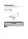
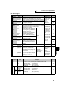
CAUTION
· Tighten the terminal screw to the specified torque.
A screw that has been tighten too loosely can cause a short circuit or malfunction.
A screw that has been tighten too tightly can cause a short circuit or malfunction due to the unit breakage.
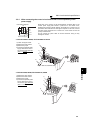
· Use crimping terminals with insulation sleeve to wire the power supply and motor.
3 × wire resistance[mΩ/m] × wiring distance[m] × current[A]
1000