


338
Causes and corrective actions
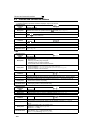
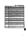
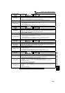
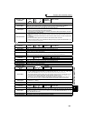
(4) Fault
When a fault occurs, the inverter trips and a fault signal is output.
Operation Panel
Indication
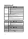
E.OC1
FR-PU04
FR-PU07(-01)
OC During Acc
Name
Overcurrent trip during acceleration
Description
When the inverter output current reaches or exceeds approximately 170% of the rated current during
acceleration, the protective circuit is activated to stop the inverter output.
Check point
⋅ Check for sudden acceleration.
⋅ Check that the downward acceleration time is not long in vertical lift application.
⋅ Check for output short circuit.
⋅ Check that the Pr. 3 Base frequency setting is not 60Hz when the motor rated frequency is 50Hz.
· Check if the stall prevention operation level is set too high.
· Check if the fast-response current limit operation is disabled.
⋅ Check that the regeneration is not performed frequently. (Check that the output voltage becomes
larger than the V/F reference voltage at regeneration and overcurrent occurs due to the high
voltage.)
⋅ Check if a start command is given to the inverter while the motor is coasting.
Corrective action
⋅ Increase the acceleration time.
(Shorten the downward acceleration time in vertical lift application.)
⋅ When "E.OC1" is always lit at starting, disconnect the motor once and start the inverter.
If "E.OC1" is still lit, contact your sales representative.
⋅ Check the wiring to make sure that output short circuit does not occur.
⋅ Set the Pr. 3 Base frequency to 50Hz. (Refer to page 89.)
· Lower the setting of stall prevention operation level. (Refer to page 81.)
· Activate the fast-response current limit operation.
⋅ Set base voltage (rated voltage of the motor, etc.) in Pr. 19 Base frequency voltage. (Refer to page 89.)
⋅ Input a start command after the motor stops. Alternatively, use the automatic restart after
instantaneous power failure/flying start function. (Refer to page 152.)
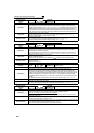
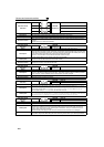
Operation Panel
Indication
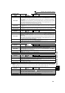
E.OC2
FR-PU04
FR-PU07(-01)
Stedy Spd OC
Name
Overcurrent trip during constant speed
Description
When the inverter output current reaches or exceeds approximately 170% of the rated current during
constant speed operation, the protective circuit is activated to stop the inverter output.
Check point
⋅ Check for sudden load change.
⋅ Check for output short circuit.
· Check if the stall prevention operation level is set too high.
· Check if the fast-response current limit operation is disabled.
⋅ Check if a start command is given to the inverter while the motor is coasting.
Corrective action
⋅ Keep load stable.
⋅ Check the wiring to avoid output short circuit.
· Lower the setting of stall prevention operation level. (Refer to page 81.)
· Activate the fast-response current limit operation.
⋅ Input a start command after the motor stops. Alternatively, use the automatic restart after
instantaneous power failure/flying start function. (Refer to page 152.)
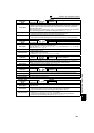
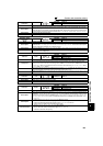
Operation Panel
Indication
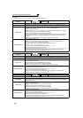
E.OC3
FR-PU04
FR-PU07(-01)
OC During Dec
Name
Overcurrent trip during deceleration or stop
Description
When the inverter output current reaches or exceeds approximately 170% of the rated inverter current
during deceleration (other than acceleration or constant speed), the protective circuit is activated to
stop the inverter output.
Check point
⋅ Check for sudden speed reduction.
⋅ Check for output short circuit.
⋅ Check for too fast operation of the motor's mechanical brake.
· Check if the stall prevention operation level is set too high.
· Check if the fast-response current limit operation is disabled.
⋅ Check if a start command is given to the inverter while the motor is coasting.
Corrective action
⋅ Increase the deceleration time.
⋅ Check the wiring to avoid output short circuit.
⋅ Check the mechanical brake operation.
· Lower the setting of stall prevention operation level. (Refer to page 81.)
· Activate the fast-response current limit operation.
⋅ Input a start command after the motor stops. Alternatively, use the automatic restart after
instantaneous power failure/flying start function. (Refer to page 152.)