


384
Heatsink protrusion attachment procedure
7.4 Heatsink protrusion attachment procedure
When encasing the inverter in an enclosure, the generated heat amount in an enclosure can be greatly reduced by
installing the heatsink portion of the inverter outside the enclosure. When installing the inverter in a compact
enclosure, etc., this installation method is recommended.
7.4.1 When using a heatsink protrusion attachment (FR-A7CN)
For the FR-F720-00105 to 04750, FR-F740-00023 to 03610, a heatsink can be protruded outside the enclosure
using a heatsink protrusion attachment (FR-A7CN). (Attachment is not required when protruding the heatsink for
FR-F740-04320 or larger inverter.) For a panel cut dimension drawing and an installation procedure of the heatsink
protrusion attachment (FR-A7CN) to the inverter, refer to a manual of "heatsink protrusion attachment (FR-A7CN01
to 11)".
7.4.2 Protrusion of heatsink of the FR-F740-04320 or more
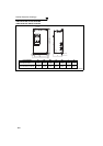
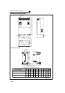
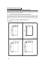
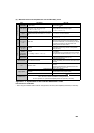
(1) Panel cutting
Cut the panel of the enclosure according to the inverter capacity.
• FR-F740-04320, 04810
(Unit: mm (inches))
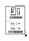
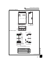
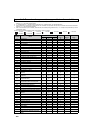
• FR-F740-05470, 06100, 06830
(Unit: mm (inches))
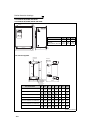
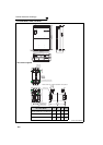
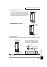
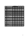
• FR-F740-07700, 08660
(Unit: mm (inches))
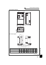
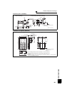
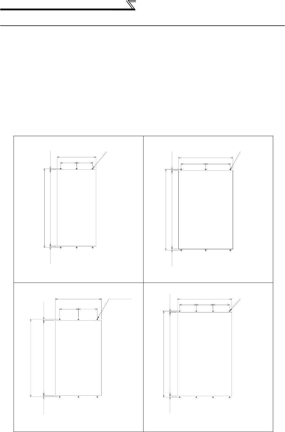
• FR-F740-09620, 10940, 12120
(Unit: mm (inches))
200(7.87) 200(7.87)
484(19.06)
13(0.51)954(37.56)
18(0.71)
985(38.78)
Hole
6-M10 screw
Hole
300(11.81) 300(11.81)
662(26.06)
15(0.59)954(37.56)15(0.59)
984(38.74)
6-M10 screw
6-M10 screw
771(30.35)
1300(51.18)
21(0.83)1258(49.53)21(0.83)
Hole
315(12.4)
315(12.4)
8-M10 screw
300(11.81) 300(11.81) 300(11.81)
976(38.43)
21(0.83)
1508(59.37)21(0.83)
1550(61.02)
Hole