


247
Communication operation and setting
4
PARAMETERS
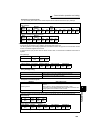
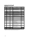
4.19.8 BACnet MS/TP protocol
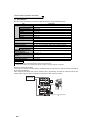
Using BACnet MS/TP protocol, communication operation and parameter setting are available from the RS-485
terminals of the inverter.
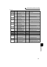
Parameter
Number
Name
Initial
Value
Setting
Range
Description
52
DU/PU main
display data
selection
0
(output
frequency)
0, 5, 6,
8 to 14, 17,
20, 23 to 25,
50 to 57, 67,
81 to 86, 100
81: BACnet reception status
82: BACnet token pass counter
(Displays the count of received token)
83: BACnet valid APDU counter
(Displays the count of valid APDU detection)
84: BACnet communication error counter
(Displays the count of communication error)
85: Terminal CA output level
(Same display as AnalogOutput0)
86: Terminal AM output level
(Same display as AnalogOutput1)
The monitor of setting value "82 and 83" return to 0 if the count
exceeds 9999. For the monitor of setting value "84", 9999 is
the maximum.
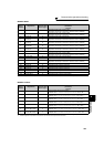
774
775
776
PU/DU monitor
selection 1
9999
1 to 3, 5, 6, 8
to 14, 17, 20,
23 to 25,
40 to 42,
50 to 57, 67,
81 to 86,
100, 9999
PU/DU monitor
selection 2
PU/DU monitor
selection 3
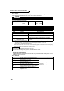
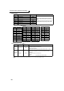
331
RS-485
communication
station number
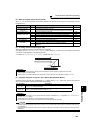
0 0 to 127 *1 Set the inverter station number (node).
332
RS-485
communication
speed
96
96, 192, 384,
768 *1 *2
Set the communication speed.
The setting value × 100 equals the communication speed.
For example, the communication speed is 9600bps when the
setting value is "96".
390
% setting reference
frequency
60Hz 1 to 400Hz Set a reference frequency of the set frequency.
549
Protocol selection
1
0 Mitsubishi inverter (computer link) protocol
1 Modbus-RTU protocol
2 BACnet MSTP protocol
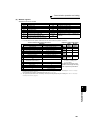
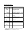
726
Auto Baudrate/Max
Master
255 0 to 255
Auto baud rate (bit7)
Setting range: 0 (Inactive)
1 (Active)
Max Master (bit0 to bit6) setting range: 0 to 127
Maximum address for master node
727
Max Info Frames
1 1 to 255
Set the maximum number of messages that the inverter can
transmit while it owns the token.
728
Device instance
number (Upper 3
digit)
0
0 to 419
(0 to 418)
Device identifier (Duplicated setting available)
Setting range of the combination of Pr. 728 and Pr. 729 are "0 to
4194302".
When Pr.728 = "419", setting range of Pr. 729 is "0 to 4302"
When Pr.729 = "4303" or more, setting range of Pr. 728 is "0 to
418"
729
Device instance
number (Lower 4
digit)
0
0 to 9999
(0 to 4302)
The above parameters can be set when Pr. 160 User group read selection = "0". (Refer to page 190)
.....Specifications differ according to the date assembled. Refer to page 400 to check the SERIAL number.
*1 The inverter works with the initial parameter setting if a value other than the setting range is set.
*2 When using Auto baudrate, the communication speed is changed to the detected communication speed.
♦ Parameters referred to ♦
Pr. 336 RS-485 communication check time interval Refer to page 214
Pr. 338 Communication operation command source Refer to page 204
Pr. 339 Communication speed command source Refer to page 204
Pr. 340 Communication startup mode selection Refer to page 203
Pr. 342 Communication EEPROM write selection Refer to page 216
Pr. 502 Modbus-RTU communication check time interval Refer to page 216
Pr. 550 NET mode operation command source selection Refer to page 204
Pr. 551 PU mode operation command source selection Refer to page 204