


224
Communication operation and setting
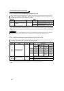
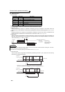
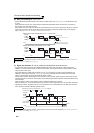
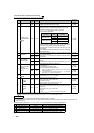
(6) Retry count setting (Pr. 121, Pr. 335)
⋅ Set the permissible number of retries at occurrence of a data receive error. (Refer to page 223 for data receive error
for retry)
⋅ When data receive errors occur consecutively and exceed the permissible number of retries set, an inverter trip
(E.PUE) may occur and stops the motor.
⋅ When "9999" is set, an inverter will not trip even if data receive error occurs but an alarm output signal (LF) is output.
For the terminal used for the LF signal output, assign the function by setting "98 (positive logic) or 198 (negative
logic)" in any of Pr. 190 to Pr. 196 (output terminal function selection).
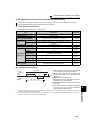
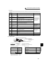
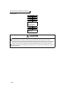
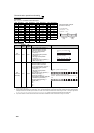
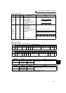
(7) Signal loss detection (Pr. 122, Pr. 336 RS-485 communication check time interval)
⋅ If a signal loss (communication stop) is detected between the inverter and computer as a result of signal loss
detection, a communication fault (PU connector communication: E.PUE, RS-485 terminal communication: E.SER)
occurs and the inverter trips.
⋅ Signal loss detection is made when the setting is any of "0.1s" to "999.8s". To make a signal loss detection, it is
necessary to send data (control code refer to page 222) from the computer within the communication check time
interval. (The send data has nothing to do with the station number)
⋅ Communication check is started at the first communication in the operation mode having the command source (PU
operation mode for PU connector communication in the initial setting or Network operation mode for RS-485 terminal
communication).
⋅ When the setting is "9999", communication check (a signal loss detection) is not made.
⋅ When the setting is "0", communication from the PU connector cannot be performed. For communication via the RS-
485 terminals, monitor, parameter read, etc. can be performed, but a communication error (E.SER) occurs as soon
as the inverter is switched to Network operation mode.
REMARKS
When using RS-485 terminal communication, inverter behavior at fault occurrence varies depending on Pr. 502 Stop mode selection
at communication error setting. (Refer to page 216)
REMARKS
When using RS-485 terminal communication, inverter behavior at fault occurrence varies depending on Pr. 502 Stop mode selection
at communication error setting. (Refer to page 216)
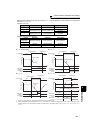
Computer
Example: PU connector communication, Pr. 121 = "1" (initial value)
Example: PU connector communication, Pr. 121 = "9999"
Reception error
Fault (E.PUE)
Inverter
Inverter
Computer
ENQ
ACK
NAK
NAK
Computer
LF OFF
Inverter
Inverter
Computer
ENQ
ACK
NAK
NAK
ON ON
Wrong
Wrong
ENQ
ACK
Normal
ENQ
Wrong
ENQ
Wrong
Reception error
Reception error
ALM
ON
Reception error
Computer
Operation Mode
Example: PU connector communication, Pr. 122 = "0.1 to 999.8s"
External
PU
Check start
Fault (E.PUE)
Time
Inverter
Inverter
Computer
Pr.122
ENQ
Communication
check counter
ALM ON