


264
PID control
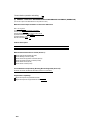
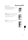
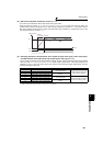
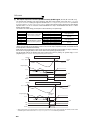
4)Reverse action
Increases the manipulated variable (output frequency) if deviation X = (set point - measured value) is positive, and
decreases the manipulated variable if deviation is negative.
5)Forward action
Increases the manipulated variable (output frequency) if deviation X = (set point - measured value) is negative, and
decreases the manipulated variable if deviation is positive.
Relationships between deviation and manipulated variable (output frequency)
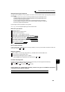
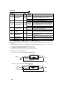
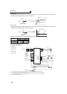
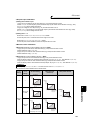
(3) Connection diagram
Deviation
Positive Negative
Reverse action
Forward action
⋅ Sink logic
⋅ Pr. 128 = 20
⋅ Pr. 183 = 14
⋅ Pr. 191 = 47
⋅ Pr. 192 = 16
⋅ Pr. 193 = 14
⋅ Pr. 194 = 15
*1 The power supply must be selected in accordance with the power specifications of the detector used.
*2 The used output signal terminal changes depending on the Pr. 190 to Pr. 196 (output terminal selection) setting.
*3 The used input signal terminal changes depending on the Pr. 178 to Pr. 189 (input terminal selection) setting.
*4 The AU signal need not be input.
Set
point
X>0
X<0
Feedback signal
(measured value)
+
-
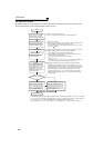
[Heating]
Deviation
Set point
Measured value
Cold
Hot
Increase
Decrease
Set
point
X>0
X<0
Feedback signal
(measured value)
+
-
[Cooling]
Deviation
Set point
Measured value
Too cold
Hot
Decrease
Increase
Power supply
MCCB
Inverter
Forward
rotation
Reverse
rotation
PID control
selection
Setting
Potentiometer
(Set point setting)
0 24V
Power
supply
*1
AC1φ
200/220V 50/60Hz
R/L1
S/L2
T/L3
STF
STR
RT(X14)
*3
10
2
5
4
*4
U
V
W
*2(FUP)FU
*2(FDN)OL
SE
(Measured value) 4 to 20mA
Motor
IM
Pump
P
Upper limit
*2(PID)SU
During PID action
Lower limit
Output signal common
2-wire type
Detector
3-wire
type
-
++ +
-
(OUT) (24V)
Forward rotation
output
Reverse rotation
output
*2(RL)IPF
1
(COM)
MC
SD