


156
Operation selection at power failure
and instantaneous power failure
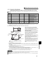
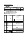
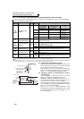
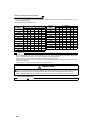
4.12.3 Power failure-time deceleration-to-stop function (Pr. 261 to Pr. 266 )
The above parameters can be set when Pr. 160 User group read selection = "0". (Refer to page 190)
....Specifications differ according to the date assembled. Refer to page 400 to check the SERIAL number.
* When the setting of Pr. 21 Acceleration/deceleration time increments is "0" (initial value), the setting range is "0 to 3600s" and the setting increments are
"0.1s", and when the setting is "1", the setting range is "0 to 360s" and the setting increments are "0.01s"
When a power failure or undervoltage occurs, the inverter can be decelerated to a stop or can be decelerated
and re-accelerated to the set frequency.
Parameter
Number
Name
Initial
Value
Setting
Range
Description
261
Power failure stop
selection
0
Operation at
undervoltage or
power failure
At power restoration
during power failure
deceleration
Deceleration time to a
stop
0
Coasts to a stop Coasts to a stop —
1
Decelerates to a stop Decelerates to a stop
Depends on Pr. 262 to
Pr. 266 settings
2
Decelerates to a stop Accelerates again
Depends on Pr. 262 to
Pr. 266 settings
21 Decelerates to a stop Decelerates to a stop
Automatically adjusts
the deceleration time
22 Decelerates to a stop Accelerates again
Automatically adjusts
the deceleration time
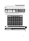
262
Subtracted frequency
at deceleration start
3Hz 0 to 20Hz
Normally operation can be performed with the initial value unchanged. But
adjust the frequency according to the magnitude of the load specifications
(moment of inertia, torque).
263
Subtraction starting
frequency
60Hz
0 to
400Hz
When output frequency ≥ Pr. 263
Decelerate from the speed obtained from output frequency minus Pr. 262.
When output frequency < Pr. 263
Decelerate from output frequency
9999 Decelerate from the speed obtained from output frequency minus Pr. 262.
264
Power-failure
deceleration time 1
5s
0 to 3600/
360s *
Set a deceleration slope down to the frequency set in Pr. 266.
265
Power-failure
deceleration time 2
9999
0 to 3600/
360s *
Set a deceleration slope below the frequency set in Pr. 266.
9999 Same slope as in Pr. 264
266
Power failure
deceleration time
switchover frequency
60Hz
0 to
400Hz
Set the frequency at which the deceleration slope is switched from the Pr. 264
setting to the Pr. 265 setting.
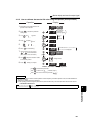
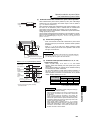
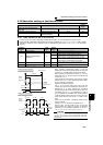
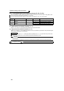
(1) Connection and parameter setting
⋅ Remove the jumpers across terminals R/L1 and R1/L11 and
across terminals S/L2 and S1/L21, and connect terminals
R1/L11 and P/+ and terminals S1/L21 and N/-.
⋅ When setting of Pr. 261 is not "0", the inverter decelerates to
a stop if an undervoltage, power failure or input phase loss
(when Pr. 872 ="1"(input phase loss enabled)) occurs.
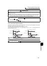
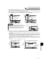
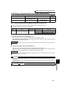
(2) Operation outline of deceleration to stop at
power failure
⋅ If an undervoltage or power failure occurs, the output
frequency is dropped by the frequency set in Pr. 262 .
⋅ Deceleration is made in the deceleration time set in Pr. 264.
(The deceleration time setting is the time required from Pr. 20
Acceleration/deceleration reference frequency to a stop.)
⋅ When the frequency is low and enough regenerative energy
is not provided, for example, the deceleration time (slope)
from Pr. 265 to a stop can be changed.
⋅ When Pr. 261 = "21, 22", inverter decelerates to stop
automatically by adjusting the deceleration time to make
converter voltage (DC bus) constant. (The setting of Pr. 262
to Pr. 266 are invalid.)
Power supply
Remove the jumper
Inverter
S/L2
T/L3
S1/L21
P/+
N/−
R1/L11
R/L1
Connect terminal
R1/L11 and P/+
and terminal
S1/L21 and N/-.
Pr.264
Power-failure
deceleration time 1
Pr.265
Power-failure
deceleration
time 2
Time
Power supply
Output
frequency
Subtracted
frequency at
deceleration start
Pr.262
Power-failure
deceleration
time switchover
frequency
P
r.266