


344
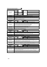
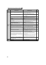
Causes and corrective actions
Operation Panel
Indication
E. 5
FR-PU04
FR-PU07(-01)
Fault 5
E. 6 Fault 6
E. 7 Fault 7
E.CPU CPU Fault
Name
CPU fault
Description Stops the inverter output if the communication fault of the built-in CPU occurs.
Check point Check for devices producing excess electrical noises around the inverter.
Corrective action
· Take measures against noises if there are devices producing excess electrical noises around the
inverter.
· Please contact your sales representative.
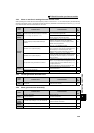
Operation Panel
Indication
E.CTE
FR-PU04
FR-PU07(-01)
E.CTE
Name
Operation panel power supply short circuit, RS-485 terminal power supply short circuit
Description
When the operation panel power supply (PU connector) is shorted, this function shuts off the power
output and stops the inverter output. At this time, the operation panel (parameter unit) cannot be used
and RS-485 communication from the PU connector cannot be made. When the internal power supply
for RS-485 terminals are shorted, this function shuts off the power output.
At this time, communication from the RS-485 terminals cannot be made.
To reset, enter the RES signal or switch power OFF, then ON again.
Check point
· Check for a short circuit in the PU connector cable.
· Check that the RS-485 terminals are connected correctly.
Corrective action
· Check the PU and cable.
· Check the connection of the RS-485 terminals
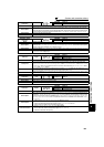
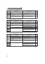
Operation Panel
Indication
E.P24
FR-PU04
FR-PU07(-01)
E.P24
Name
24VDC power output short circuit
Description
When the 24VDC power output from the PC terminal is shorted, this function shuts off the power output.
At this time, all external contact inputs switch OFF. The inverter cannot be reset by entering the RES
signal. To reset it, use the operation panel or switch power OFF, then ON again.
Check point · Check for a short circuit in the PC terminal output.
Corrective action · Remedy the earth (ground) fault portion.
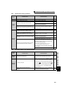
Operation Panel
Indication
E.CDO
FR-PU04 Fault 14
FR-PU07(-01) OC detect level
Name
Output current detection value exceeded
Description
This functions stops the inverter output when the output current exceeds the setting of Pr.150 Output
current detection level, or the output current falls below the setting of Pr.152 Zero current detection level.
This function is active when Pr. 167 Output current detection operation selection is set to "1, 10, 11".
When the initial value (Pr. 167 = "0") is set, this fault does not occur.
Check point
Check the settings of Pr. 150 Output current detection level, Pr. 151 Output current detection signal delay
time, Pr. 152 Zero current detection level, Pr. 153 Zero current detection time, Pr. 166 Output current detection
signal retention time, Pr. 167 Output current detection operation selection. (Refer to page 135.)
Operation Panel
Indication
E.IOH
FR-PU04 Fault 14
FR-PU07(-01) Inrush overheat
Name
Inrush current limit circuit fault
Description
Trips when the resistor of the inrush current limit circuit overheats. The inrush current limit circuit fault
Check point
· Check that frequent power ON/OFF is not repeated.
· Check that no meltdown is found in the primary side fuse (5A) in the power supply circuit of the
inrush current suppression circuit contactor (FR-F740-03250 or more) or no fault is found in the
power supply circuit of the contactor.
· Check that the power supply circuit of inrush current limit circuit contactor is not damaged.
Corrective action
Configure a circuit where frequent power ON/OFF is not repeated.
If the problem still persists after taking the above measure, please contact your sales representative.