


150
Monitor display and monitor output signal
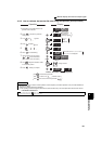
(2) AM terminal calibration (C1(Pr.901))
⋅ Calibrate the AM terminal in the following procedure.
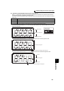
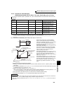
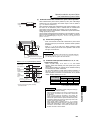
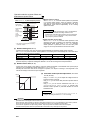
1) Connect a 0-10VDC meter (frequency meter) to across inverter terminals AM and 5. (Note the polarity. The
terminal AM is positive.)
2) Refer to the monitor description list (page 142) and set Pr. 158.
When you selected the running frequency or inverter output current as the monitor, preset the running frequency
or current value, at which the output signal will be 10V, to Pr. 55 or Pr. 56.
3) When outputting the item that cannot achieve a 100% value easily by operation, e.g. output current, set "21"
(reference voltage output) in Pr. 158 and perform the following operation. After that, set "2" (output current, for
example) in Pr. 158.
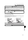
⋅ Terminal AM is factory-set to provide a 10VDC output in the full-scale
status of the corresponding monitor item. Calibration parameter C1 (Pr.
901) allows the output voltage ratios (gains) to be adjusted according to
the meter scale. Note that the maximum output voltage is 10VDC.
REMARKS
⋅ When calibrating a monitor output signal, which cannot be adjusted to 100% value without an actual load and a measurement
equipment, set Pr. 158 to "21" (reference voltage output).
10VDC is output from the terminal AM.
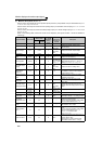
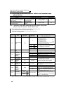
♦ Parameters referred to ♦
Pr. 54 CA terminal function selection Refer to page 147
Pr. 55 Frequency monitoring reference Refer to page 147
Pr.56 Current monitoring reference Refer to page 147
Pr.158 AM terminal function selection Refer to page 147
AM
Inverter
10VDC
5