


173
Frequency setting by analog input (terminal 1, 2, 4)
4
PARAMETERS
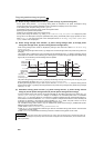
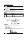
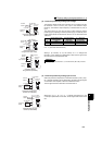
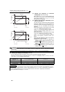
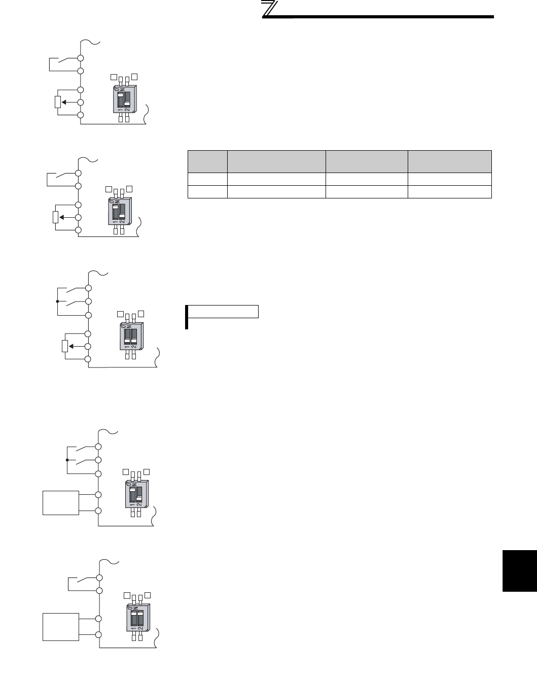
(2) Perform operation by analog input voltage
⋅ The frequency setting signal inputs 0 to 5VDC (or 0 to 10VDC) to across
the terminals 2 and 5. The 5V (10V) input is the maximum output
frequency. The maximum output frequency is reached when 5V (10V) is
input.
⋅ The power supply 5V (10V) can be input by either using the internal
power supply or preparing an external power supply. The internal power
supply outputs 5VDC across terminals 10 and 5, or 10V across terminals
10E and 5.
⋅ When inputting 10VDC to the terminal 2, set any of "0, 2, 4, 10, 12, 14"
in Pr. 73. (The initial value is 0 to 5V)
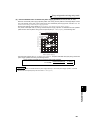
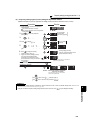
⋅ Setting "1 (0 to 5VDC)" or "2 (0 to 10VDC)" in Pr. 267 changes the
terminal 4 to the voltage input specification. When the AU signal turns
ON, the terminal 4 input becomes valid.
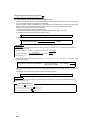
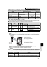
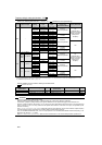
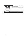
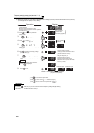
(3) Perform operation by analog input current
⋅ When the pressure or temperature is controlled constant by a fan, pump,
etc., automatic operation can be performed by inputting the output signal
4 to 20mADC of the adjuster to across the terminals 4 and 5.
⋅ The AU signal must be turned ON to use the terminal 4.
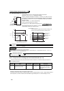
⋅ Setting any of "6, 7, 16, 17" in Pr. 73 changes the terminal 2 to the
current input specification. At this time, the AU signal need not be turned
ON.
STF
Inverter
Forward
rotation
Frequency
setting
0 to 5VDC
10
2
5
Connection diagram using
terminal 2 (0 to 5VDC)
Voltage/current
input switch
SD
2
4
STF
Inverter
Forward
rotation
Frequency
setting
0 to 10VDC
10E
2
5
Connection diagram
using terminal 2 (0 to 10VDC)
Voltage/current
input switch
SD
2
4
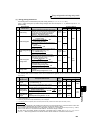
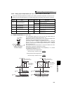
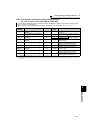
Terminal
Inverter Built-in Power
Supply Voltage
Frequency Setting
Resolution
Pr. 73 (terminal 2
input voltage)
10 5VDC 0.030Hz/60Hz 0 to 5VDC input
10E 10VDC 0.015Hz/60Hz 0 to 10VDC input
STF
SD
AU
DC0 to 5V
10
4
5
2
4
Forward
rotation
Frequency
setting
Terminal 4
input selection
Inverter
Voltage/current
input switch
Connection diagram
using terminal 4 (0 to 5VDC)
REMARKS
The wiring length of the terminal 10, 2, 5 should be 30m (98.4 feet) maximum.
STF
Inverter
Forward
rotation
Frequency
setting
4
5
AU
Connection diagram using
terminal 4 (4 to 20mADC)
4 to 20mADC
Current
input
equipment
Voltage/current
input switch
2
4
SD
STF
SD
2
5
2
4
Forward
rotation
Frequency
setting
Current
input
equipment
Inverter
Voltage/current
input switch
Connection diagram using
terminal 2 (4 to 20mADC)
4 to 20mADC