


27
Control circuit specifications
2
WIRING
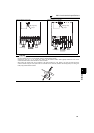
2.3 Control circuit specifications
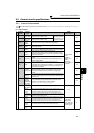
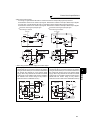
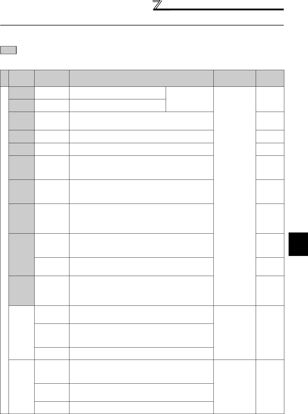
2.3.1 Control circuit terminals
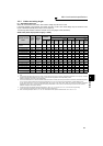
indicates that terminal functions can be selected using Pr. 178 to Pr. 196 (I/O terminal function selection) (Refer to page 122.)
(1) Input signals
Type
Terminal
Symbol
Terminal
Name
Description
Rated
Specifications
Refer to
Contact input
STF
Forward
rotation start
Turn ON the STF signal to start forward
rotation and turn it OFF to stop.
When the STF and
STR signals are turned
ON simultaneously, the
stop command is given.
Input resistance
4.7kΩ
Voltage at
opening: 21 to
27VDC
Contacts at
short-circuited: 4
to 6mADC
122
STR
Reverse
rotation start
Turn ON the STR signal to start reverse
rotation and turn it OFF to stop.
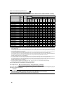
STOP
Start self-
holding
selection
Turn ON the STOP signal to self-hold the start signal. 122
RH,
RM, RL
Multi-speed
selection
Multi-speed can be selected according to the combination of RH,
RM and RL signals.
122
JOG
Jog mode
selection
Turn ON the JOG signal to select Jog operation (initial setting)
and turn ON the start signal (STF or STR) to start Jog operation.
122
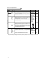
RT
Second
function
selection
Turn ON the RT signal to select second function.
When the second function such as "second torque boost" and
"second V/F (base frequency)" are set, turning ON the RT signal
selects these functions.
122
MRS Output stop
Turn ON the MRS signal (20ms or more) to stop the inverter
output.
Use to shut off the inverter output when stopping the motor by
electromagnetic brake.
122
RES Reset
Used to reset fault output provided when fault occurs.
Turn ON the RES signal for more than 0.1s, then turn it OFF.
Initial setting is for reset always. By setting Pr.75, reset can be set
to enabled only at fault occurrence. Inverter recovers about 1s
after the reset is released.
122
AU
Terminal 4
input selection
Terminal 4 is valid only when the AU signal is turned ON. (The
frequency setting signal can be set between 0 and 20mADC.)
Turning the AU signal ON makes terminal 2 (voltage input)
invalid.
171
PTC input
AU terminal is used as PTC input terminal (thermal protection of
the motor). When using it as PTC input terminal, set the AU/PTC
switch to PTC.
110
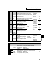
CS
Selection of
automatic
restart after
instantaneous
power failure
When the CS signal is left ON, the inverter restarts automatically at
power restoration. Note that restart setting is necessary for this
operation. In the initial setting, a restart is disabled.
(Refer to page
152
for Pr. 57 Restart coasting time)
122
SD
Contact input
common (sink)
(initial setting)
Common terminal for contact input terminal (sink logic)
-------------------- —
External
transistor
common
(source)
When connecting the transistor output (open collector output), such
as a programmable controller, when source logic is selected, connect
the external power supply common for transistor output to this
terminal to prevent a malfunction caused by undesirable currents.
24VDC power
supply common
Common output terminal for 24VDC 0.1A power supply (PC terminal).
Isolated from terminals 5 and SE.
PC
External
transistor
common (sink)
(initial setting)
When connecting the transistor output (open collector output), such
as a programmable controller, when sink logic is selected, connect
the external power supply common for transistor output to this
terminal to prevent a malfunction caused by undesirable currents.
Power supply
voltage range
19.2 to 28.8VDC
Permissible load
current 100mA
31
Contact input
common
(source)
Common terminal for contact input terminal (source logic).
24VDC power
supply
Can be used as 24VDC 0.1A power supply.