


367
6
PRECAUTIONS FOR MAINTENANCE AND INSPECTION
Measurement of main circuit voltages,
currents and powers
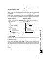
6.2.7 Measurement of converter output voltage (across terminals P/+ and N/-)
The output voltage of the converter is developed across terminals P/+ and N/- and can be measured with a moving-
coil type meter (tester). Although the voltage varies according to the power supply voltage, approximately 270V to 300V
(approximately 540V to 600V for the 400V class) is output when no load is connected and voltage decreases when a
load is connected.
When regenerative energy is returned from the motor during deceleration, for example, the converter output voltage
rises to nearly 400V to 450V (800V to 900V for the 400V class) maximum.
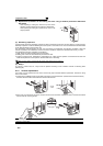
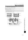
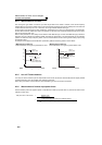
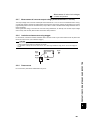
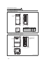
6.2.8 Insulation resistance test using megger
For the inverter, conduct the insulation resistance test on the main circuit only as shown below and do not perform the
test on the control circuit. (Use a 500VDC megger.)
6.2.9 Pressure test
Do not conduct a pressure test. Deterioration may occur.
CAUTION
• Before performing the insulation resistance test on the external circuit, disconnect the cables from all terminals of the
inverter so that the test voltage is not applied to the inverter.
• For the electric continuity test of the control circuit, use a tester (high resistance range) and do not use the megger or
buzzer.
U
V
W
Inverter
500VDC
megger
Power
supply
IM
Moto
r
R/L1
S/L2
T/L3
Ground