


109
Selection and protection of a motor
4
PARAMETERS
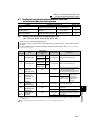
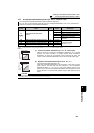
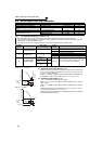
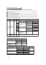
(3) Set multiple electronic thermal relay functions (Pr. 51)
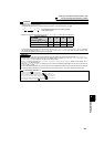
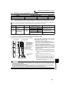
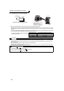
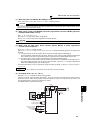
(4) Electronic thermal relay function prealarm (TH) and alarm signal (THP signal)
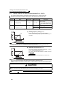
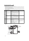
(5) External thermal relay input (OH signal)
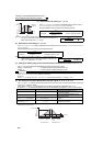
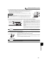
Use this function when rotating two motors of different rated currents individually by a
single inverter. (When rotating two motors together, use external thermal relays.)
⋅ Set the rated current of the second motor in Pr. 51.
⋅ When the RT signal is ON, thermal protection is provided based on the Pr. 51 setting.
100%: Electronic thermal relay function alarm operation value
⋅ The alarm signal (THP) is output and electronic thermal relay
function prealarm (TH) is displayed when the electronic
thermal value reaches 85% of the level set in Pr. 9 or Pr. 51. If
it reaches 100% of the Pr. 9 Electronic thermal O/L relay
setting, an electronic thermal relay protection (E.THM/E.THT)
activates.
⋅ The inverter does not trip even when the alarm signal (THP)
is output.
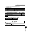
⋅ For the terminal used for the THP signal output, assign the
function by setting "8" (positive logic) or "108" (negative logic)
in any of Pr. 190 to Pr. 196 (output terminal function selection).
CAUTION
⋅ Changing the terminal assignment using Pr. 190 to Pr. 196 (output terminal function selection) may affect the other functions. Set
parameters after confirming the function of each terminal.
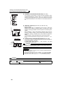
External thermal relay input
connection example
⋅ To protect the motor against overheat, use the OH signal when using an external
thermal relay or the built-in thermal protector of the motor.
⋅ When the thermal relay operates, the inverter trips and outputs the fault signal
(E.OHT).
⋅ For the terminal used for OH signal input, assign the function by setting "7" in any of
Pr. 178 to Pr. 189 (input terminal function selection)
CAUTION
⋅ Changing the terminal assignment using Pr. 178 to Pr. 189 (input terminal function selection) may affect the other functions. Set
parameters after confirming the function of each terminal.
REMARKS
⋅ The RT signal acts as the second function selection signal and makes the other second
functions valid. (Refer to page 124)
⋅ The RT signal is assigned to the RT terminal in the initial setting. By setting "3" in any of Pr. 178
to Pr. 189 (input terminal function selection), you can assign the RT signal to the other terminal.
RT
MC
MC
W
V
U
IM
IM
SD
OFF
ON
100%
85%
Time
ON
Electronic thermal
relay function
operation level
Electronic thermal O/L
relay alarm
(THP)
Inverter
U
V
W
OH
Thermal relay protecto
r
Motor
IM
SD