


261
PID control
4
PARAMETERS
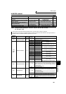
4.20 PID control
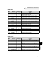
4.20.1 Outline of PID control (Pr. 127 to Pr. 134, Pr. 241, Pr. 553, Pr. 554,
Pr. 575 to Pr. 577)
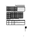
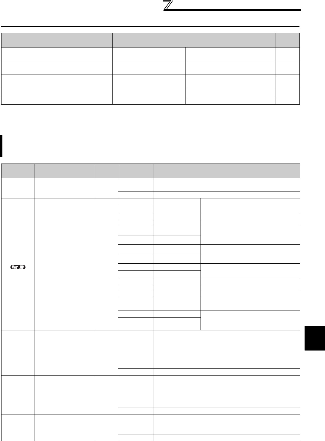
Purpose Parameter that must be Set
Refer
to Page
Perform process control such as pump and
air volume.
Outline of PID control
Pr. 127 to Pr. 134, Pr. 553, Pr. 554,
Pr. 575 to Pr. 577
261
Calibrate the measured value input and PID
display coefficient
Bias and gain calibration for
PID displayed values
Pr. 241, Pr. 759,
C42 (Pr. 934) to C45 (Pr. 935)
273
Drive a motor at a constant speed before
starting to PID control
Pre-charge function Pr. 760 to Pr. 769 275
Switch between two PID control settings
Second PID function Pr. 753 to Pr. 758, Pr. 765 to Pr. 769 281
Pump function by multiple motors Advanced PID function Pr. 554, Pr. 575 to Pr. 591 283
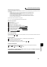
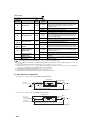
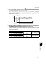
The inverter can be used to exercise process control, e.g. flow rate, air volume or pressure.
The terminal 2 input signal or parameter setting is used as a set point and the terminal 4 input signal used as a
feedback value to constitute a feedback system for PID control.
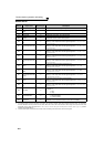
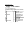
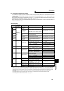
Parameter
Number
Name
Initial
Value
Setting
Range
Description
127
PID control automatic
switchover frequency
9999
0 to 400Hz
Set the frequency at which the control is automatically
changed to PID control.
9999 Without PID automatic switchover function
128
PID action selection 10
10, 110
*2 PID reverse action
Deviation value signal input
(terminal 1 *4)
11, 111
*2 PID forward action
20, 120
*2 PID reverse action
Measured value (terminal 4
*5)
Set point (terminal 2
*4 or Pr. 133)
21, 121
*2 PID forward action
50
*2 PID reverse action
Deviation value signal input
(L
ON
W
ORKS
, CC-Link, BACnet)
51 *2 PID forward action
60
*2 PID reverse action
Measured value, set point input
(L
ON
W
ORKS
, CC-Link, BACnet)
61 *2 PID forward action
70
*6 PID reverse action
Deviation value signal input
(PLC function)
71
*6 PID forward action
80
*6 PID reverse action
Measured value, set point input
(PLC function)
81
*6 PID forward action
90
*6 PID reverse action Deviation value signal input
(PLC function)
(Not applied to the inverter frequency)
91
*6 PID forward action
100
*6 PID reverse action Measured value, set point input
(PLC function)
(Not applied to the inverter frequency)
101
*6 PID forward action
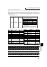
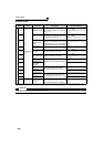
129
*1 PID proportional band 100%
0.1 to 1000%
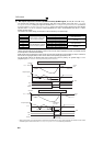
If the proportional band is narrow (parameter setting is small), the
manipulated variable varies greatly with a slight change of the
measured value. Hence, as the proportional band narrows, the
response sensitivity (gain) improves but the stability deteriorates,
e.g. hunting occurs.
Gain Kp = 1/proportional band
9999 No proportional control
130
*1 PID integral time 1s
0.1 to 3600s
When deviation step is input, time (Ti) is the time required for
integral (I) action to provide the same manipulated variable as
proportional (P) action.
As the integral time decreases, the set point is reached earlier but
hunting occurs more easily.
9999 No integral control.
131 PID upper limit 9999
0 to 100% *3
Set the upper limit value. If the feedback value exceeds the
setting, the FUP signal is output. The maximum input (20mA/5V/
10V) of the measured value (terminal 4) is equivalent to 100%.
9999 No function