


218
Communication operation and setting
REMARKS
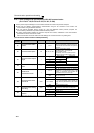
⋅ Fault output indicates the fault output signal (ALM signal) and an alarm bit output.
⋅ When the fault output setting is active, a fault record is saved in the faults history. (A fault record is written to the faults history at a
fault output. )
When the fault output setting is not active, a fault record is overwritten to the faults history temporarily but not stored.
After the error is removed, the fault indication goes back to normal indication in the monitor, and the faults history goes back to the
previous status.
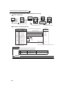
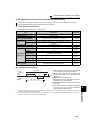
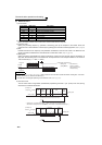
⋅ If Pr. 502 is set to "1, 2, or 3," the normal deceleration time setting (settings like Pr. 8, Pr. 44, and Pr. 45) is applied as the
deceleration time. Normal acceleration time setting (settings like Pr. 7 and Pr. 44) is applied as the acceleration time for restart.
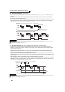
⋅ When Pr.502 = "2 or 3," the inverter operates with the start command and the speed command, which were used before the error.
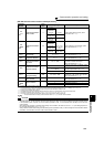
⋅ If a communication line error occurs, then the error is removed during deceleration while Pr. 502 = "2," the motor re-accelerates
as soon as the error is removed.
⋅ These parameters are valid when communication is performed from the RS-485 terminals or a communication option.
⋅ These parameters are valid under the Network operation mode. When performing communication with RS-485 terminals, set Pr.
551
PU mode operation command source selection="2 (initial setting)."
⋅ Pr. 502 is valid for the device that has the command source under the Network operation mode. If a communication option is
installed while Pr. 550 = "9999 (initial setting)," a communication error in RS-485 terminals occurs and Pr. 502 becomes invalid.
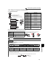
⋅ If the communication error setting is disabled with Pr. 502 = "3," Pr. 335 = "9999," and Pr. 539 = "9999," the inverter does not
continue its operation with the frequency set by Pr. 779 at a communication error.
⋅ If a communication error occurs while continuous operation at Pr. 779 is selected with Pr. 502 = "3," the inverter operates at the
frequency set in Pr. 779 even though the speed command source is at the external terminals.
Example) If a communication error occurs while Pr. 339 = "2" and the external terminal RL is ON, the operation is continued at the
frequency set in Pr. 779.
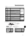
♦ Parameters referred to ♦
Pr. 7 Acceleration time Pr. 8 Deceleration time Refer to page 101
Pr. 335 RS-485 communication retry count
Refer to page 214
Pr. 336 RS-485 communication check time interval
Refer to page 214
Pr. 539 Modbus-RTU communication check time interval
Refer to page 232
Pr. 550 NET mode operation command source selection
Refer to page 204
Pr. 551 PU mode operation command source selection Refer to page 204