


127
Function assignment of external
terminal and control
4
PARAMETERS
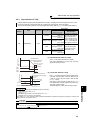
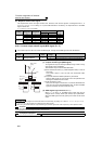
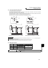
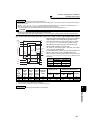
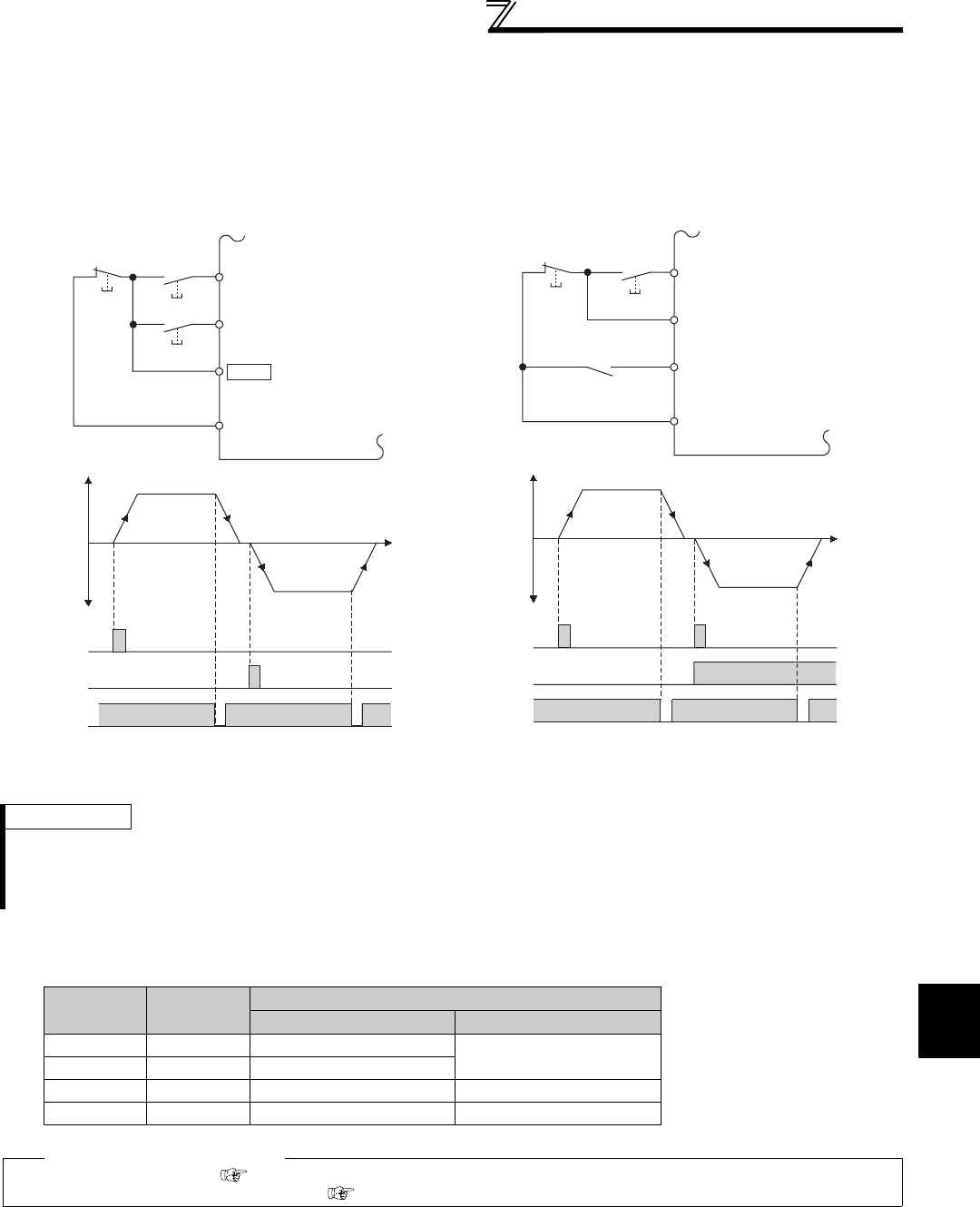
(2) 3-wire type (STF, STR, STOP signal)
⋅ A 3-wire type connection is shown below.
⋅ The start self-holding selection becomes valid when the STOP signal is turned ON. In this case, the forward/
reverse rotation signal functions only as a start signal.
⋅ If the start signal (STF or STR) is turned ON and then OFF, the start signal is held and makes a start. When
changing the direction of rotation, turn STR (STF) ON once and then OFF.
⋅ To stop the inverter, turning OFF the STOP signal once decelerates it to a stop.
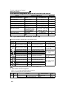
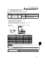
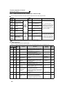
(3) Start signal selection
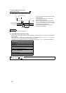
3-Wire Type Connection Example (Pr. 250 ="9999")
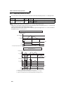
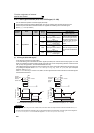
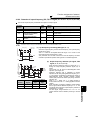
3-Wire Type Connection Example (Pr. 250 ="8888")
REMARKS
⋅ The STOP signal is assigned to the terminal STOP in the initial setting. By setting "25" in Pr. 178 to Pr. 189, the STOP signal can
also be assigned to the other terminal.
⋅ When the JOG signal is turned ON to enable jog operation, the STOP signal becomes invalid.
⋅ If the MRS signal is turned ON to stop the output, the self-holding function is not canceled.
STF STR
Pr. 250 Setting Inverter Status
0 to 100s, 9999 1000s to 1100s, 8888
OFF OFF Stop
Stop
OFF ON Reverse rotation
ON OFF Forward rotation Forward rotation
ON ON Stop Reverse rotation
♦ Parameters referred to ♦
Pr. 4 to Pr. 6 (Multi-speed setting) Refer to page 93
Pr. 178 to Pr. 189 (Input terminal function selection) Refer to page 122
Stop
Forward
rotation start
Reverse
rotation start
STF
STR
STOP
Inverter
Time
STF
STR
ON
STOP
OFF
Output frequency
ON
Forward
rotation
Reverse
rotation
OFF
ON
SD
Time
Stop
Forward rotation
/reverse rotation
Start
STF
STR
ON
STOP
ON
STF
STR
STOP
Inverter
Output frequency
ON
ON
OFF OFF
Forward
rotation
Reverse
rotation
SD