


137
Function assignment of external
terminal and control
4
PARAMETERS
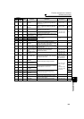
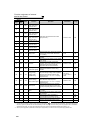
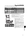
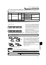
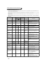
4.10.8 Remote output function (REM signal, Pr. 495 to Pr. 497)
You can utilize the ON/OFF of the inverter's output signals instead of the remote output terminal of the
programmable controller.
Parameter
Number
Name
Initial
Value
Setting
Range
Description
495
Remote output selection 0
0
Remote output data clear at
powering OFF
Remote output data clear at
inverter reset
1
Remote output data retention
even at powering OFF
10
Remote output data clear at
powering OFF
Remote output data retention
even at inverter reset
11
Remote output data retention
even at powering OFF
496 * Remote output data 1 0 0 to 4095
Refer to the following diagram.
497 * Remote output data 2 0 0 to 4095
The above parameters can be set when Pr. 160 User group read selection = "0". (Refer to page 190)
... Specifications differ according to the date assembled. Refer to page 400 to check the SERIAL number.
* The above parameters allow its setting to be changed during operation in any operation mode even if "0" (initial value) is set in Pr. 77 Parameter write
selection.
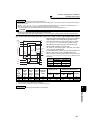
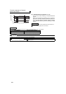
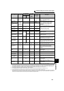
<Remote output data>
Pr. 496
Pr. 497
*1 As desired
*2 Y0 to Y6 are available only when the extension output option (FR-A7AY) is fitted
*3 RA1 to RA3 are available only when the relay output option (FR-A7AR) is fitted
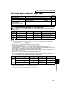
⋅ The output terminal can be turned ON/OFF depending
on the Pr. 496 or Pr. 497 setting. The remote output
selection can be controlled ON/OFF by computer link
communication from the PU connector or RS-485 port
or by communication from the communication option.
⋅ Set "96" (positive logic) or "196" (negative logic) in any
of Pr. 190 to Pr. 196 (output terminal function selection),
and assign the remote output (REM) signal to the
terminal used for remote output,
⋅ When you refer to the left diagram and set 1 to the
terminal bit (terminal where the REM signal has been
assigned) of Pr. 496 or Pr. 497, the output terminal
turns ON (OFF for negative logic). By setting 0, the
output terminal turns OFF (ON for negative logic).
Example)When "96" (positive logic) is set to Pr. 190 RUN terminal function selection and "1" (H01) is set to Pr. 496,
the terminal RUN turns ON.
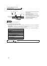
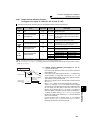
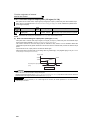
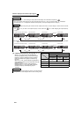
⋅
When
Pr. 495
= "0 (initial value), 10", performing a power
supply reset (including a power failure) clears the REM signal
output. (The ON/OFF status of the terminals are as set in
Pr.
190 to Pr. 196
.) The
Pr. 496
and
Pr. 497
settings are also "0".
When
Pr. 495
= "1, 11", the remote output data before power
supply-OFF is stored into the EEPROM, so the signal output
at power recovery is the same as before power supply-OFF.
However, it is not stored when the inverter is reset (terminal
reset, reset request through communication).
(See the chart on the left)
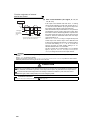
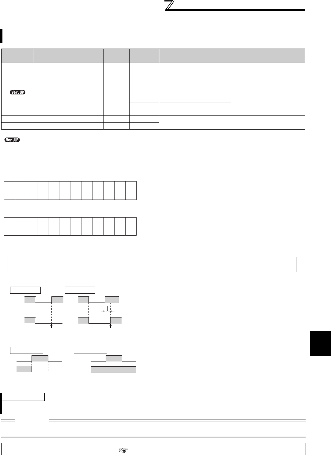
⋅
When
Pr. 495
= "10, 11", the signal during reset is held even an
inverter reset is made.
REMARKS
⋅ The output terminal where the REM signal is not assigned using any of Pr. 190 to Pr. 196 does not turn ON/OFF if 0/1 is set to
the terminal bit of Pr. 496 or Pr. 497. (It turns ON/OFF with the assigned function.)
CAUTION
⋅ When Pr. 495="1, 11"(remote output data retention at power OFF), connect R1/11 with P/+, and S1/L21 with N/- so that the
control power is retained. If you do not take such a step, the output signals provided after power-ON are not guaranteed.
♦ Parameters referred to ♦
⋅ Pr. 190 to Pr. 196 (output terminal function selection) Refer to page 128
b11 b0
ABC1
ABC2
*1
*1
*1
*1
*1
FU
OL
IPF
SU
RUN
b11 b0
Y5 *2
Y6 *2
RA1 *3
RA2 *3
RA3 *3
*1
*1
Y4 *2
Y3 *2
Y2 *2
Y1 *2
Y0 *2
Power
supply
Power
supply
OFF OFF
ONOFF
REMREM
REM signal clear REM signal held
Inverter
reset time
(about 1s)
Pr. 495 = 0, 10
Pr. 495 = 1, 11
ON
ON
OFF
REM
*
ON
ON
REM
ON/OFF example for positive logic
Signal condition during a reset
Reset
Reset
Pr. 495 = 0, 1 Pr. 495 = 10, 11
* When
Pr. 495
= "1," the signal condition saved in
EEPROM (condition of the last power OFF) is applied.