


303
Useful functions
4
PARAMETERS
(4) Main circuit capacitor life display (Pr. 258, Pr. 259)
⋅ The deterioration degree of the main circuit capacitor is displayed in Pr. 258 as a life.
⋅ On the assumption that the main circuit capacitor capacitance at factory shipment is 100%, the capacitor life is
displayed in Pr. 258 every time measurement is made. When the measured value falls to or below 85%, Pr. 255 bit 1
is turned ON and also an alarm is output to the Y90 signal.
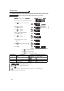
⋅ Measure the capacitor capacity according to the following procedure and check the deterioration level of the
capacitor capacity.
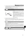
1) Check that the motor is connected and at a stop.
2) Set "1" (measuring start) in Pr. 259
3) Switch power OFF. The inverter applies DC voltage to the motor to measure the capacitor capacity while the
inverter is OFF.
4) After making sure that the power lamp is OFF, switch ON the power supply again.
5) Check that "3" (measuring completion) is set in Pr. 259, read Pr .258, and check the deterioration degree of the
main circuit capacitor.
(5) Cooling fan life display
⋅ The cooling fan speed of 50% or less is detected and "FN" is displayed on the operation panel (FR-DU07) and
parameter unit (FR-PU04/FR-PU07). As an alarm display, Pr. 255 bit 2 is turned ON and also an alarm is output to
the Y90 signal.
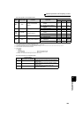
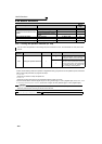
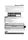
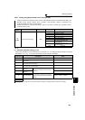
Pr. 259 Description Remarks
0
No measurement Initial value
1 Measurement start
Measurement starts when the
power supply is switched OFF.
2 During measurement
Only displayed and cannot be
set
3 Measurement complete
8 Forced end
9 Measurement error
REMARKS
⋅ When the main circuit capacitor life is measured under the following conditions, "forced end" (Pr. 259 = "8") or "measuring error"
(Pr. 259 ="9") occurs or it remains in "measuring start" (Pr. 259 = "1").
When measuring, avoid the following conditions beforehand. In addition, even when "measurement completion" (Pr. 259 = "3")
is confirmed under the following conditions, proper measurement cannot be taken.
(a)The FR-HC, MT-HC, FR-CV, MT-RC or sine wave filter is connected
(b)Terminals R1/L11, S1/L21 or DC power supply is connected to the terminal P/+ and N/-.
(c) Switch power ON during measuring.
(d)The motor is not connected to the inverter.
(e)The motor is running. (The motor is coasting.)
(f) The motor capacity is two rank smaller as compared to the inverter capacity.
(g)The inverter is tripped or a fault occurred while power is OFF.
(h)The inverter output is shut off with the MRS signal.
(i) The start command is given while measuring.
⋅ Operating environment: Surrounding air temperature (annual average 40°C (104°F) (free from corrosive gas, flammable gas, oil
mist, dust and dirt))
Output current (80% of the inverter rated current)
POINT
For the accurate life measuring of the main circuit capacitor, perform after more than 3h passed since the turn OFF
of the power as it is affected by the capacitor temperature.
WARNING
When measuring the main circuit capacitor capacity (Pr. 259 Main circuit capacitor life measuring = "1"), the DC
voltage is applied to the motor for 1s at powering OFF. Never touch the motor terminal, etc. right after powering
OFF to prevent an electric shock.
REMARKS
⋅ When the inverter is mounted with two or more cooling fans, "FN" is displayed with one or more fans with speed of 50% or less.
CAUTION
⋅ For replacement of each part, contact the nearest Mitsubishi FA center.