


58
Operation panel (FR-DU07)
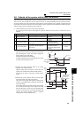
4.1 Operation panel (FR-DU07)
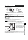
4.1.1 Component of the operation panel (FR-DU07)
To mount the operation panel (FR-DU07) on the enclosure surface, refer to page 34.
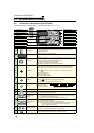
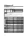
No. Component Name Description
(a) Unit indicator
Hz: Lit to indicate frequency. (Flickers when the set frequency monitor is displayed.)
A: Lit to indicate current.
V: Lit to indicate voltage.
(b)
Monitor (4-digit LED)
Shows the frequency, parameter number, etc.
(To monitor the output power, the set frequency and other items, set Pr. 52, Pr. 774 to
Pr. 776. )
(c)
Setting dial
The dial of the Mitsubishi inverters. The setting dial is used to change the frequency and
parameter settings.
Press the setting dial to perform the following operations:
⋅ To display a set frequency in the monitor mode
⋅ To display the present setting during calibration
⋅ To display a fault history number in the faults history mode
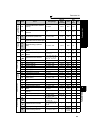
(d)
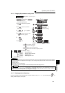
PU/EXT key
Used to switch between the PU and External operation modes.
To use the External operation mode (operation using a separately connected frequency
setting potentiometer and start signal), press this key to light up the EXT indicator.
(Press simultaneously (0.5s), or change the Pr.79 setting to change to the
combined operation mode. )
PU: PU operation mode
EXT: External operation mode
Used to cancel the PU stop also.
(e)
MODE key
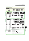
Used to switch among different setting modes.
Pressing simultaneously changes the operation mode.
Holding this key for 2 seconds locks the operation panel.
(f)
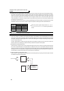
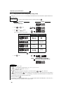
SET key
Used to enter a setting.
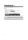
If pressed during the
operation, monitored item
changes as the following:
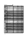
(g)
Monitor indicator
Lit to indicate the monitor mode.
(h) PLC function indicator
Lit to indicate that the PLC function is active.
(i)
Operation mode
indicator
PU: Lit to indicate the PU operation mode.
EXT: Lit to indicate the External operation mode. (EXT is lit at power-ON in the initial setting.)
NET: Lit to indicate the Network operation mode.
PU and EXT: Lit to indicate EXT/PU combined operation mode 1 and 2
(j)
Rotation direction
indicator
FWD: Lit to indicate the forward rotation.
REV: Lit to indicate the reverse rotation.
Lit: When the forward/reverse operation is being performed.
Flickers: When the frequency command is not given even if the forward/reverse command is given.
When the frequency command is lower than the starting frequency.
When the MRS signal is being input.
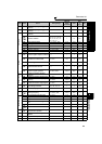
(k)
FWD key, REV key
FWD key: Used to give a start command in forward rotation.
REV key: Used to give a start command in reverse rotation.
(l) STOP/RESET key
Used to stop operation commands.
Used to reset a fault when the protective function (fault) is activated.
(a) Unit indicator
(b) Monitor (4-digit LED)
(c) Setting dial
(d) PU/EXT key
(e) MODE key
(f) SET key
(g) Monitor indicator
(h) PLC function indicator
(i) Operation mode indicator
(
j
) Rotation direction indicator
(k) FWD key, REV key
(l) STOP/RESET key
Output frequency → Output current → Output voltage*
* Energy saving monitor is displayed when the
energy saving monitor is set with Pr. 52.