


123
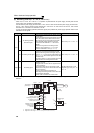
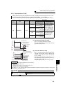
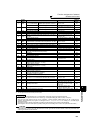
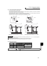
Function assignment of external
terminal and control
4
PARAMETERS
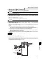
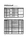
*1 When Pr. 59 Remote function selection ≠ "0", the functions of the RL, RM and RH signals change as listed above.
*2 The OH signal turns ON when the relay contact "opens".
1RM
Pr. 59 = 0 (initial value) Middle-speed operation command
Pr. 4 to Pr. 6, Pr. 24 to Pr. 27, Pr.
232 to Pr. 239
93
Pr. 59 ≠ 0
*1 Remote setting (deceleration) Pr. 59 98
2RH
Pr. 59 = 0 (initial value) High-speed operation command
Pr. 4 to Pr. 6, Pr. 24 to Pr. 27, Pr.
232 to Pr. 239
93
Pr. 59 ≠ 0
*1 Remote setting (acceleration) Pr. 59 98
3 RT Second function selection Pr. 44 to Pr. 51 125
4 AU Terminal 4 input selection Pr. 267 171
5 JOG Jog operation selection Pr. 15, Pr. 16 95
6CS
Selection of automatic restart after instantaneous power failure,
flying start
Pr. 57, Pr. 58, Pr.162 to Pr.165,
Pr. 299, Pr. 611
152
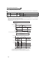
Electronic bypass function
Pr. 57, Pr. 58 Pr. 135 to Pr. 139, Pr. 159
293
7 OH External thermal relay input
*2 Pr. 9 107
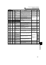
8 REX 15-speed selection (combination with three speeds RL, RM, RH)
Pr. 4 to Pr. 6, Pr. 24 to Pr. 27,
Pr.232 to Pr.239
93
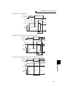
10 X10 Inverter run enable signal (FR-HC, MT-HC, FR-CV connection) Pr. 30 114
11 X11
FR-HC or MT-HC connection, instantaneous power failure detection
Pr. 30 114
12 X12 PU operation external interlock Pr. 79 195
13 X13 External DC injection brake operation start Pr. 11, Pr. 12 112
14 X14 PID control valid terminal
Pr. 127 to Pr. 134, Pr. 575 to Pr. 577
261
16 X16
PU/External operation switchover
(turning ON X16 selects External operation)
Pr. 79, Pr. 340 201
24 MRS
Output stop Pr. 17 124
Electronic bypass function
Pr. 57, Pr. 58, Pr. 135 to Pr. 139, Pr. 159
293
25 STOP Start self-holding selection ⎯ 126
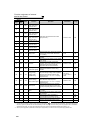
50 SQ Sequence start
Pr. 414, Pr. 415, Pr. 498,
Pr. 506 to Pr. 515
260
51 X51 Fault clear signal ⎯ 332
60 STF
Forward rotation command
(assigned to STF terminal (Pr. 178) only)
⎯ 126
61 STR
Reverse rotation command
(assigned to STR terminal (Pr. 179) only)
⎯ 126
62 RES Inverter reset ⎯⎯
63 PTC PTC thermistor input (assigned to AU terminal (Pr. 184) only) Pr. 9 107
64 X64 PID forward/reverse action switchover Pr. 127 to Pr. 134 261
65 X65
PU/NET operation switchover
(turning ON X65 selects PU operation)
Pr. 79, Pr. 340 203
66 X66
External/NET operation switchover
(turning ON X66 selects NET operation)
Pr. 79, Pr. 340 203
67 X67
Command source switchover
(Pr.338 and Pr.339 commands are valid when X67 turns ON)
Pr. 338, Pr. 339 204
70 X70 DC feeding operation permission
Pr. 30, Pr. 70
114
71 X71 DC feeding cancel
Pr. 30, Pr. 70
114
72 X72 PID integral value reset
Pr. 127 to Pr. 134, Pr. 241, Pr.
553, Pr. 554, Pr. 575 to Pr. 577,
C42 to C45
261
77 X77 Pre-charge end command
Pr. 127 to Pr. 130, Pr. 133,
Pr. 134, Pr. 760 to Pr. 764
275
78 X78 Second pre-charge end command Pr. 753 to Pr. 758, Pr. 765 to Pr. 769 275
9999 ⎯ No function ⎯⎯
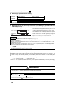
REMARKS
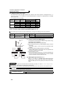
⋅ Same function can be assigned to two or more terminals. In this case, the logic of terminal input is OR.
⋅ The priorities of the speed commands are in order of jog > multi-speed setting (RH, RM, RL, REX) > PID (X14).
⋅ When the X10 signal (FR-HC, MT-HC, FR-CV connection - inverter operation enable signal) is not set or when the PU
operation external interlock (X12) signal is not assigned at the Pr. 79 Operation mode selection setting of "7", the MRS signal
shares this function.
⋅ Same signal is used to assign multi-speeds (7 speeds) and remote setting. They cannot be set individually.
(Same signal is used since multi-speed (7 speeds) setting and remote setting are not used to set speed at the same time .)
CAUTION
⋅ Changing the terminal assignment using Pr. 178 to Pr. 189 (input terminal function selection) may affect the other functions. Also
check that wiring is correct, since the terminal name and the signal function became different. Please set parameters after
confirming the function of each terminal.
Setting
Signal
Name
Function Related Parameters
Refer to
Page