


176
Frequency setting by analog input (terminal 1, 2, 4)
(2) Override function (Pr. 252, Pr. 253)
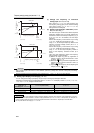
4.16.3 Response level of analog input and noise elimination (Pr. 74)
The above parameters can be set when Pr. 160 User group read selection = "0". (Refer to page 190)
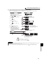
⋅ Effective for eliminating noise in the frequency setting circuit.
⋅ Increase the filter time constant if steady operation cannot be performed due to noise. A larger setting results in
slower response. (The time constant can be set between approximately 5ms to 1s with the setting of 0 to 8.)
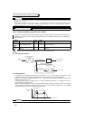
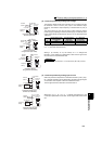
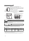
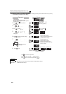
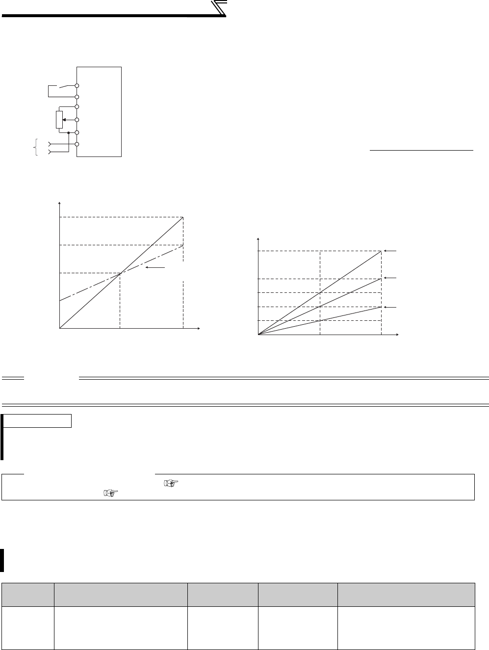
Override connection diagram
⋅ Use the override function to change the main speed at a fixed ratio.
⋅ Set any of "4, 5, 14, 15" in Pr. 73 to select an override.
⋅ When an override is selected, the terminal 1 or terminal 4 is used for the main
speed setting and the terminal 2 for the override signal. (When the main speed of
the terminal 1 or terminal 4 is not input, compensation made by the terminal 2
becomes invalid.)
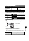
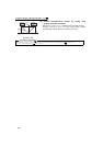
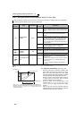
⋅ Using Pr. 252 and Pr. 253, set the override range.
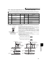
⋅ How to find the set frequency for override
Set frequency (Hz) = Main speed set frequency (Hz) ×
Main speed set frequency (Hz): Terminal 1, 4 input, multi-speed setting
Compensation amount (%): Terminal 2 input
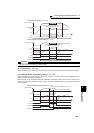
Example)When Pr. 73 = "5"
The set frequency changes as shown below according to the
terminal 1 (main speed) and terminal 2 (auxiliary) inputs.
CAUTION
⋅ When the Pr. 73 setting was changed, check the voltage/current input switch setting. Different setting may cause a fault, failure
or malfunction. (Refer to page 171 for setting.)
REMARKS
⋅ The AU signal must be turned ON to use the terminal 4.
⋅ When inputting compensation to multi-speed operation or remote setting, set "1" (compensation made) to Pr. 28 Multi-speed
input compensation selection. (Initial value is "0")
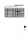
♦ Parameters referred to ♦
Pr. 28 Multi-speed input compensation selection Refer to page 97
Pr. 73 Analog input selection Refer to page 171
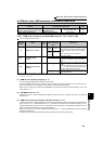
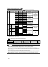
The time constant of the primary delay filter relative to external frequency command (analog input (terminal 1,
2, 4) signal) can be set.
Parameter
Number
Name Initial Value Setting Range Description
74 Input filter time constant 1 0 to 8
Set the primary delay filter time
constant for the analog input. A
larger setting results in slower
response.
10
2
5
Forward
rotation
Main
speed
Inverter
STF
1
(-)
(+)
Override
setting
SD
Compensation amount (%)
100(%)
P
r.252
0V 2.5V
(5V)
5V
(10V)
0
50
100
150
200
Initial value
(50% to 150%)
Voltage across terminals 2 and 5
P
r.253
Override value (%)
0 2.5 5
0
Terminal 1 input voltage (V)
Set frequency (Hz)
Terminal 2 5VDC
input(150%)
Terminal 2 0V
input(50%)
Terminal 2 2.5VDC
input(100%)
30
15
60
45
90