


229
Communication operation and setting
4
PARAMETERS
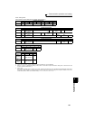
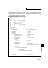
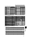
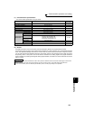
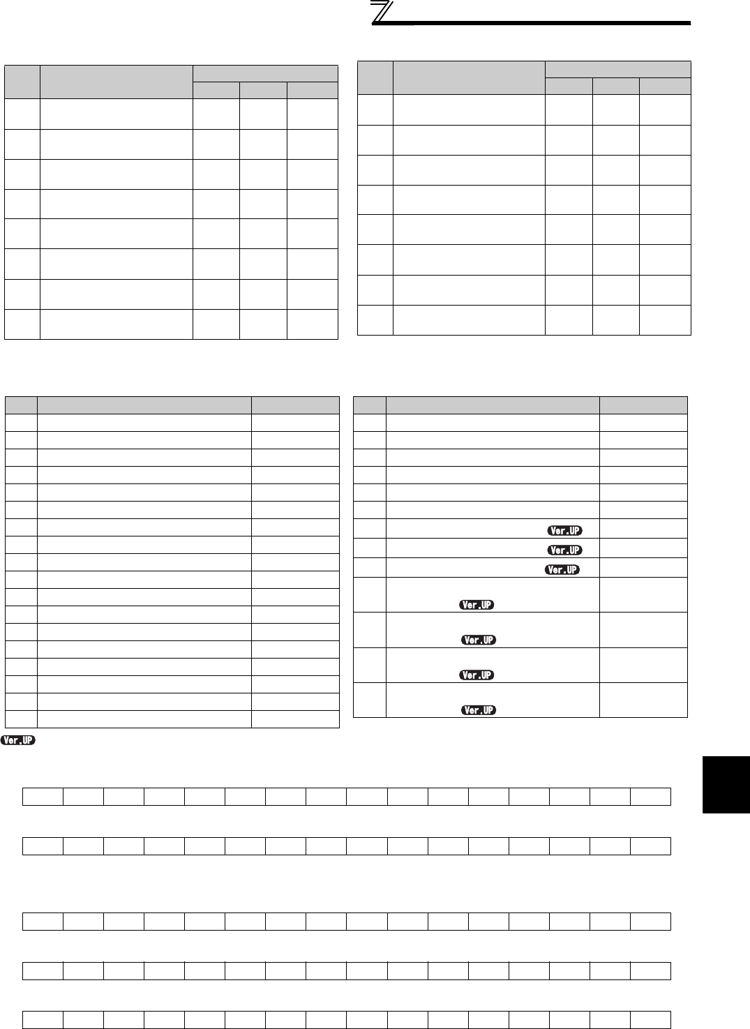
List of calibration parameters
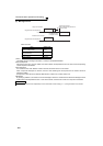
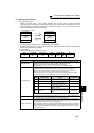
[Special monitor selection No.]
Refer to page 141 for details of the monitor description.
....Specifications differ according to the date assembled. Refer to page 400 to check the SERIAL number.
*1 The setting depends on capacities. (FR-F720-02330 (FR-F740-01160) or less/FR-F720-03160 (FR-F740-01800) or more)
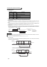
*2 Input terminal monitor details
*3 Output terminal monitor details
*5 Option input terminal 1 monitor details (input terminal status of FR-A7AX)-all terminals are OFF when an option is not fitted
*6 Option input terminal 2 monitor details (input terminal status of FR-A7AX)-all terminals are OFF when an option is not fitted
*7 Option output terminal monitor details (output terminal status of FR-A7AY)-all terminals are OFF when an option is not fitted
b15 b0
⎯⎯⎯⎯CS RES
STOP
MRS JOG RH RM RL RT AU STR STF
b15 b0
⎯⎯⎯⎯⎯⎯⎯⎯⎯
ABC2 ABC1
FU OL IPF SU RUN
*4 When Pr.37 = "1 to 9998" or Pr. 144 = "2 to 10, 102 to 110," the unit is an integral value (one increment). (Refer to page 139)
b15 b0
X15 X14 X13 X12 X11 X10 X9 X8 X7 X6 X5 X4 X3 X2 X1 X0
b15 b0
⎯⎯⎯⎯⎯⎯⎯⎯⎯⎯⎯⎯⎯⎯⎯DY
b15 b0
⎯⎯⎯⎯⎯⎯
RA3
RA2 RA1 Y6 Y5 Y4 Y3 Y2 Y1 Y0
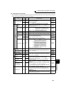
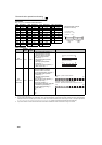
Para
meter
Name
Instruction code
Read Write
Extended
C2
(902)
Terminal 2 frequency
setting bias frequency
5E DE 1
C3
(902)
Terminal 2 frequency
setting bias
5E DE 1
125
(903)
Terminal 2 frequency
setting gain frequency
5F DF 1
C4
(903)
Terminal 2 frequency
setting gain
5F DF 1
C5
(904)
Terminal 4 frequency
setting bias frequency
60 E0 1
C6
(904)
Terminal 4 frequency
setting bias
60 E0 1
126
(905)
Terminal 4 frequency
setting gain frequency
61 E1 1
C7
(905)
Terminal 4 frequency
setting gain
61 E1 1
C8
(930)
Current output bias signal
1E 9E 9
C9
(930)
Current output bias current
1E 9E 9
C10
(931)
Current output gain signal
1F 9F 9
C11
(931)
Current output gain current
1F 9F 9
C42
(934)
PID display bias coefficient
22 A2 9
C43
(934)
PID display bias analog
value
22 A2 9
C44
(935)
PID display gain coefficient
23 A3 9
C45
(935)
PID display gain analog
value
23 A3 9
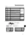
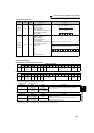
Para
meter
Name
Instruction code
Read Write
Extended
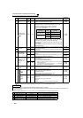
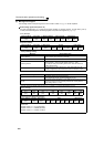
Data Description Unit
H01 Output frequency/speed
*4 0.01Hz/1
H02 Output current 0.01A/0.1A *1
H03 Output voltage 0.1V
H05 Frequency setting value/speed setting
*4 0.01Hz/1
H06 Running speed 1r/min
H08 Converter output voltage 0.1V
H09 Regenerative brake duty 0.1%
H0A
Electronic thermal relay function load factor
0.1%
H0B Output current peak value 0.01A/0.1A
*1
H0C
Converter output voltage peak value
0.1V
H0D Input power
0.01kW/0.1kW
*1
H0E Output power
0.01kW/0.1kW
*1
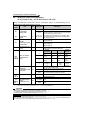
H0F Input terminal status *2 ⎯
H10 Output terminal status
*3 ⎯
H11 Load meter
0.1%
H14 Cumulative energization time
1h
H17 Actual operation time
1h
H18 Motor load factor
0.1%
H19 Cumulative power 1kWh
H32 Power saving effect Variable
H33 Cumulative saving power Variable
H34 PID set point
0.1%
H35 PID measured value
0.1%
H36 PID deviation
0.1%
H3A
Option input terminal status 1
*5
⎯
H3B
Option input terminal status 2
*6
⎯
H3C
Option output terminal status
*7
⎯
H4D
32-bit cumulative power
(lower 16-bit)
1kWh
H4E
32-bit cumulative power
(upper 16-bit)
1kWh
H4F
32-bit cumulative power
(lower 16-bit)
0.01kWh/
0.1kWh
*1
H50
32-bit cumulative power
(upper 16-bit)
0.01kWh/
0.1kWh
*1
Data Description Unit