


228
Communication operation and setting
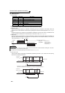
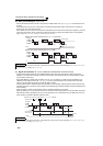
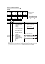
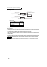
Example) When reading the C3 (Pr. 902) and C6 (Pr. 904) settings from the inverter of station No. 0
To read/write C3 (Pr. 902) and C6 (Pr. 904) after inverter reset or parameter clear, execute from 1) again.
7
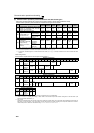
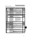
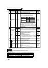
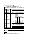
Faults history batch
clear
Write HF4 H9696: clears the faults history in batch
4 digits
(A,C/D)
8
Parameter clear
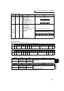
All parameter clear
Write HFC
All parameters return to the initial values.
Whether to clear communication parameters or not can be
selected according to data. (
: clear, ×: not clear)
Refer to page 390 for parameter clear, all clear, and
communication parameters.
When clear is executed for H9696 or H9966, communication-
related parameter settings also return to the initial values.
When resuming operation, set the parameters again.
Executing clear will clear the instruction code HEC, HF3, and
HFF settings.
Only H9966 and H55AA (all parameter clear) are valid during
the password lock.
4 digits
(A,C/D)
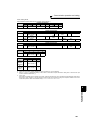
9
Parameters
Read
H00 to
H63
Refer to the instruction code (page 390) and write and/or read
the values as required.
When setting
Pr.100 and later, link parameter expansion setting
must be set.
4 digits
(B,E/D)
10 Write
H80 to
HE3
4 digits
(A,C/D)
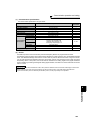
11
Link parameter
extended setting
Read H7F
Parameter description is changed according to the H00 to H09
setting.
For details of the setting, refer to the instruction code (page 390).
2digits
(B,E1/D)
Write HFF
2digits
(A1,C/D)
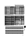
12
Second parameter
changing
(instruction code
HFF=1)
Read H6C
When setting the calibration parameters
*1
H00:Frequency *2
H01: Parameter-set analog value
H02: Analog value input from terminal
*1 Refer to the list of calibration parameters on the next page for
calibration parameters.
*2 The gain frequency can also be written using Pr. 125 (instruction
code H99) or Pr. 126 (instruction code H9A).
2digits
(B,E1/D)
Write HEC
2digits
(A1,C/D)
13
Multi command
Write/
Read
HF0
Available for writing 2 commands, and monitoring 2 items for
reading data (Refer to page 231 for detail)
10 digits
(A2,C1/D)
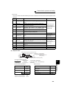
14
Inverter type monitor
Inverter type
Read H7C
Reading inverter type in ASCII code.
"H20" (blank code) is set for blank area
Example of FR-F720
H46, H52, H2D, H46, H37, H32, H30, H20.. H20
20 digits
(B,E3/D)
Capacity
Read H7D
Reading inverter capacity in ASCII code.
Data is read in increments of 0.1kW, and rounds down to 0.01kW
increments
"H20" (blank code) is set for blank area
Example
0.75K................" 7" (H20, H20, H20, H20, H20, H37)
6 digits
(B,E2/D)
Refer to page 220 for data formats (A, A1, A2, B, C, C1, D, E, E1, E2, E3, F)
....Specifications differ according to the date assembled. Refer to page 400 to check the SERIAL number.
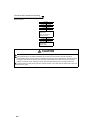
REMARKS
⋅ Set 65520 (HFFF0) as a parameter value "8888" and 65535 (HFFFF) as "9999".
⋅ For the instruction codes HFF, HEC and HF3, their values are held once written but cleared to zero when an inverter reset or all
clear is performed.
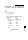
Computer Send Data Inverter Send Data Description
1)
ENQ 00 FF 0 01 82 ACK 00 Set "H01" in the extended link parameter.
2)
ENQ 00 EC 0 01 7E ACK 00 Set "H01" in second parameter changing.
3)
ENQ 00 5E 0 0F STX 00 0000 ETX 25 C3 (Pr. 902) is read. 0% is read.
4) ENQ 00 60 0 FB STX 00 0000 ETX 25 C6 (Pr. 904) is read. 0% is read.
No. Item
Read
/write
Instruction
Code
Data Description
Number of
Data Digits
(format)
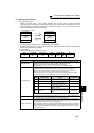
Clear type Data
Communication
parameters
Parameter clear
H9696
H5A5A
×
All parameter clear
H9966
H55AA
×